
Torsional vibration damping system for a motor vehicle drive train, hybrid drive module, and motor vehicle drive train

a technology of torsional vibration and damping system, which is applied in the direction of vehicle sub-unit features, mechanical equipment, transportation and packaging, etc., can solve the problems of reducing ride comfort, high component load, and damage to components, so as to prevent the damper unit, prevent the increase of churning loss and oil churning, and reduce assembly complexity

Active Publication Date: 2020-11-03
ZF FRIEDRICHSHAFEN AG
View PDF18 Cites 0 Cited by
  • Summary
  • Abstract
  • Description
  • Claims
  • Application Information

AI Technical Summary

Benefits of technology

[0012]The wording that the damper unit and the vibration damper are designed for placement in a wet space means, in this case, that the damper unit and the vibration damper are adapted, with respect to their lubrication, to be placed in a wet space of a housing. Thus, the damper unit and the vibration damper are supplied with oil, in particular, from radially inwardly, and, thereafter, the oil is easily discharged radially toward the outside. As compared to an arrangement of the damper unit and the vibration damper in a dry space, a lubricant supply of these components can therefore be implemented without the need to prevent the lubricant from escaping radially toward the outside.
[0014]Such a configuration of a torsional vibration damping system has the advantage in this case that a better damping of torsional vibrations in the motor vehicle drive train can be achieved by providing two torsional vibration dampers. This is the case because the arrangement of two torsional vibration dampers makes it possible to reduce the torsional rigidity of the damper unit. Overall, in the case of a torsional vibration damping system configured according to example aspects of the invention, a reliable damping of torsional vibrations can be achieved while simultaneously reliably lubricating components of the system.
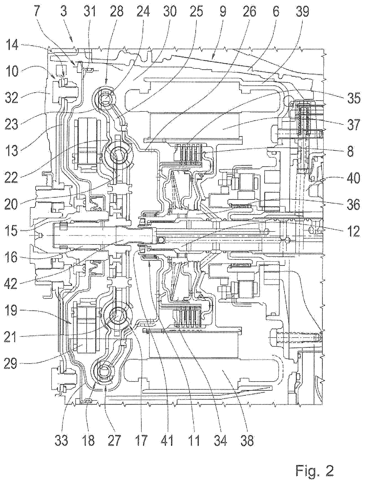
[0020]According to one further design option of the invention, the damper unit and / or the vibration damper are radially enclosed, at least in a vertically lower area, by a stationary shell. In other words, a stationary shell is therefore provided, which lies vertically lower than the damper unit and / or the vibration damper and, there, radially encloses the damper unit or the vibration damper or both. Advantageously, the shell prevents the damper unit and the vibration damper from plunging vertically downward too deeply in lubricant and prevents increased churning losses and a churning of the oil from occurring. This is the case because, due to the shell, an area having a lower lubricant level can be created in the area of the damper unit and the vibration damper than in the surrounding area of the wet space. It is particularly preferred when the shell is utilized when the torsional vibration dampers are arranged in a plane. In addition, the shell preferably surrounds the damper unit and the vibration damper.
[0021]According to one further embodiment of the invention, a hollow shaft is provided on the input side of the torsional vibration damping system, into which one further shaft is inserted and is rotationally fixed thereto. Via the further shaft, a connection to the damper unit and the vibration damper is established, wherein a sealing plate is mounted on the hollow shaft, which is utilized for separating the wet space from a dry space of the housing. In one refinement of this embodiment, the hollow shaft and the further shaft are connected to one another via a driving toothing which is implemented as an interference fit. With the aid of the interference fit, the situation is prevented in which shifting can occur in the driving toothing and, therefore, a noise generation in the area of the torsional vibration damping system can occur in the course of load changes in the drive train, especially since torsional vibrations in the area of the driving toothing have not yet been damped.
[0022]It is further preferred that the hollow shaft, the further shaft, the damper unit, the vibration damper, and the sealing plate form a preassembled unit. This has the advantage that, despite the driving toothing which is implemented as an interference fit, the sealing plate can be arranged, including a seal, on the hollow shaft. Moreover, the formation of a preassembled unit reduces the complexity of assembly, since, in the course of assembly, this unit merely needs to be arranged in the motor vehicle drive train.
[0024]By providing a torsional vibration damping system configured according to example aspects of the invention including two torsional vibration dampers, a suitable damping of torsional vibrations can also be achieved in the area of a hybrid drive module. In addition, various functions can be implemented with the aid of the electric machine of the hybrid drive module, in that the electric machine is operated as a generator or as an electric motor. In this way, the electric machine, when operated as an electric motor, can assist the drive machine by delivering an additional drive torque (boosting) or even achieve a purely electric driving operation. In addition, a start-stop function can be implemented via the electric machine, in that the electric machine starts the internal combustion engine as part of the starting process. When the electric machine is operated as a generator, current can be generated via the drive machine, during the operation, or current can even be recuperated in the course of the braking operation (recuperation). During the purely electric driving operation and also the recuperation, the connection to the drive machine is to be disconnected, in each case, by disengaging the separating clutch.

Problems solved by technology

Since torsional vibrations significantly diminish the ride comfort and can also result in a high component load up to damage to the component, measures are usually taken in a motor vehicle drive train for damping and, therefore, reducing torsional vibrations.

Method used


Image

  • Torsional vibration damping system for a motor vehicle drive train, hybrid drive module, and motor vehicle drive train
  • Torsional vibration damping system for a motor vehicle drive train, hybrid drive module, and motor vehicle drive train

Examples


Embodiment Construction

[0034]Reference will now be made to embodiments of the invention, one or more examples of which are shown in the drawings. Each embodiment is provided by way of explanation of the invention, and not as a limitation of the invention. For example, features illustrated or described as part of one embodiment can be combined with another embodiment to yield still another embodiment. It is intended that the present invention include these and other modifications and variations to the embodiments described herein.

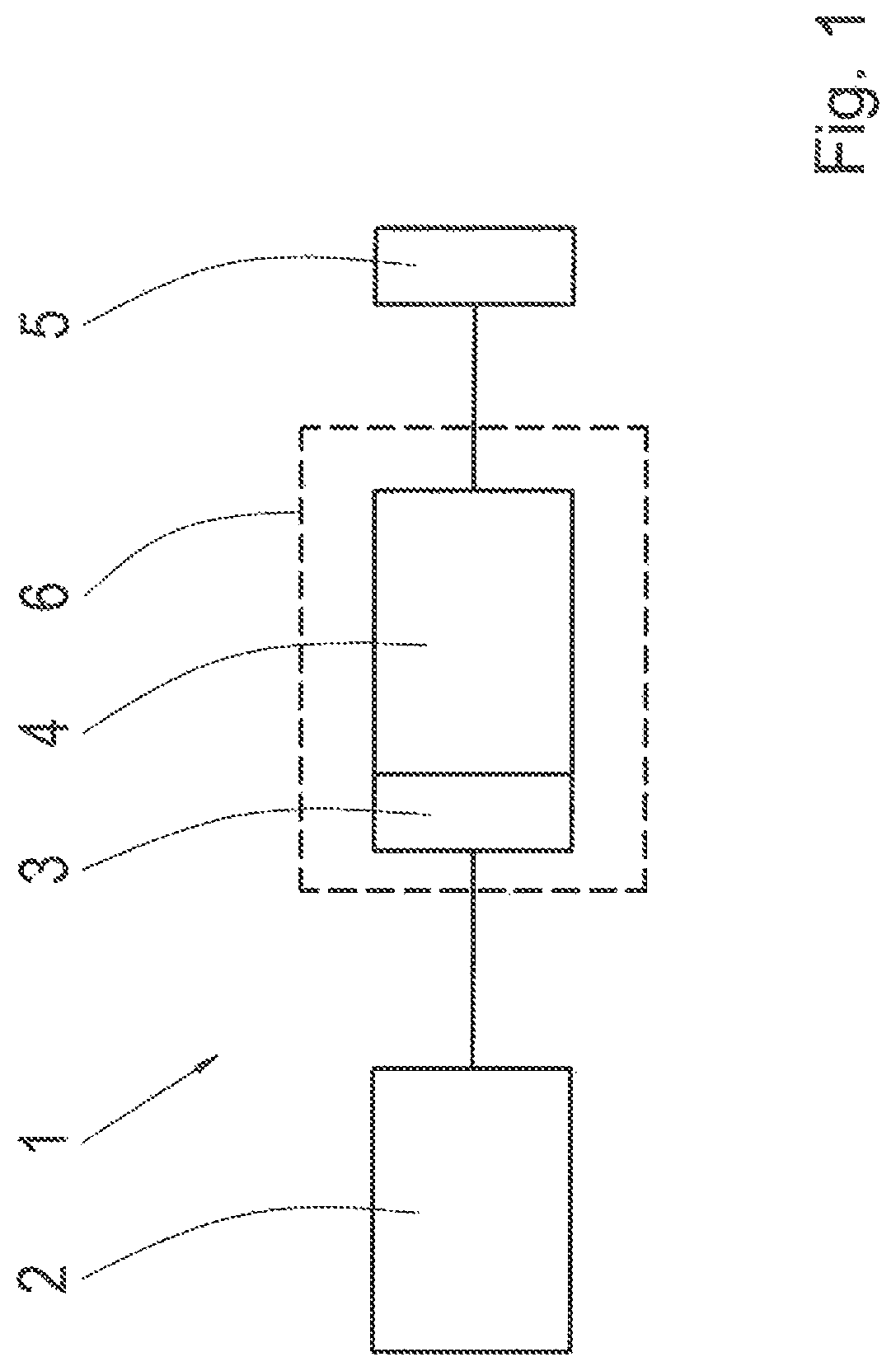
[0035]FIG. 1 shows a schematic view of a motor vehicle drive train 1 which is, in particular, the drive train of a motor vehicle in the form of a passenger car. The motor vehicle drive train 1 includes a drive machine 2 in the form of an internal combustion engine which is connectable, on the output side, to a motor vehicle transmission 4 via an intermediate hybrid drive module 3.

[0036]The motor vehicle transmission 4 is preferably configured as an automatic transmission of a plan...


PUM


Abstract

A torsional vibration damping system (7) for a motor vehicle drive train (1) has an input side (14) and an output side (26) connected via a damper unit (27). The damper unit (27) includes two torsional vibration dampers (17, 18) and a vibration damper (19). The damper unit (27) are configured for placement in a wet space (30) of a housing (6).

Description

FIELD OF THE INVENTION[0001]The invention relates generally to a torsional vibration damping system for a motor vehicle drive train, having an input side and an output side which are connected via a damper unit including at least one torsional vibration damper and a vibration damper, wherein the damper unit and the vibration damper are designed for placement in a wet space of a housing.[0002]Moreover, the invention relates generally to a hybrid drive module including a housing, in which a torsional vibration damping system and an electric machine are accommodated, wherein the torsional vibration damping system including a damper unit and a vibration damper which are provided between an input side and an output side of the torsional vibration damping system and are placed in a wet space of the housing, wherein the torsional vibration damping system is connected at its output side to a separating clutch, via which the torsional vibration damping system is connectable to an output side...

Claims


Application Information

Patent Timeline
Patent Type & Authority Patents(United States)
IPC IPC(8): B60K6/48F16F15/14B60K6/40F16F15/123F16F15/134
CPCB60K6/48F16F15/145B60K6/40F16F15/13469F16F15/12353B60Y2400/48B60K2006/4825Y02T10/62
Inventor FÜHRER, KIMCUDOK, MATTHIASRIEDISSER, THOMASMÜLLER, THORSTENSTROPH, STEPHAN
Owner ZF FRIEDRICHSHAFEN AG
Learn More