
Steering shaft

a technology of steering shaft and inner shaft, which is applied in the direction of mechanical equipment, couplings, transportation and packaging, etc., can solve the problems that the inner shaft has not been able to effectively solve the problem of vibration of the steering shaft, and the prior art vibration is known to affect the transmission of vibrations, so as to achieve the effect of preventing vibration transmission

Inactive Publication Date: 2015-09-08
ROBERT BOSCH AUTOMOTIVE STEERING
View PDF5 Cites 4 Cited by
  • Summary
  • Abstract
  • Description
  • Claims
  • Application Information

AI Technical Summary

Benefits of technology

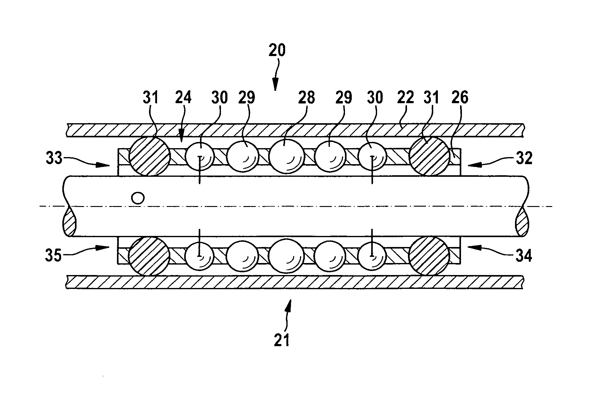
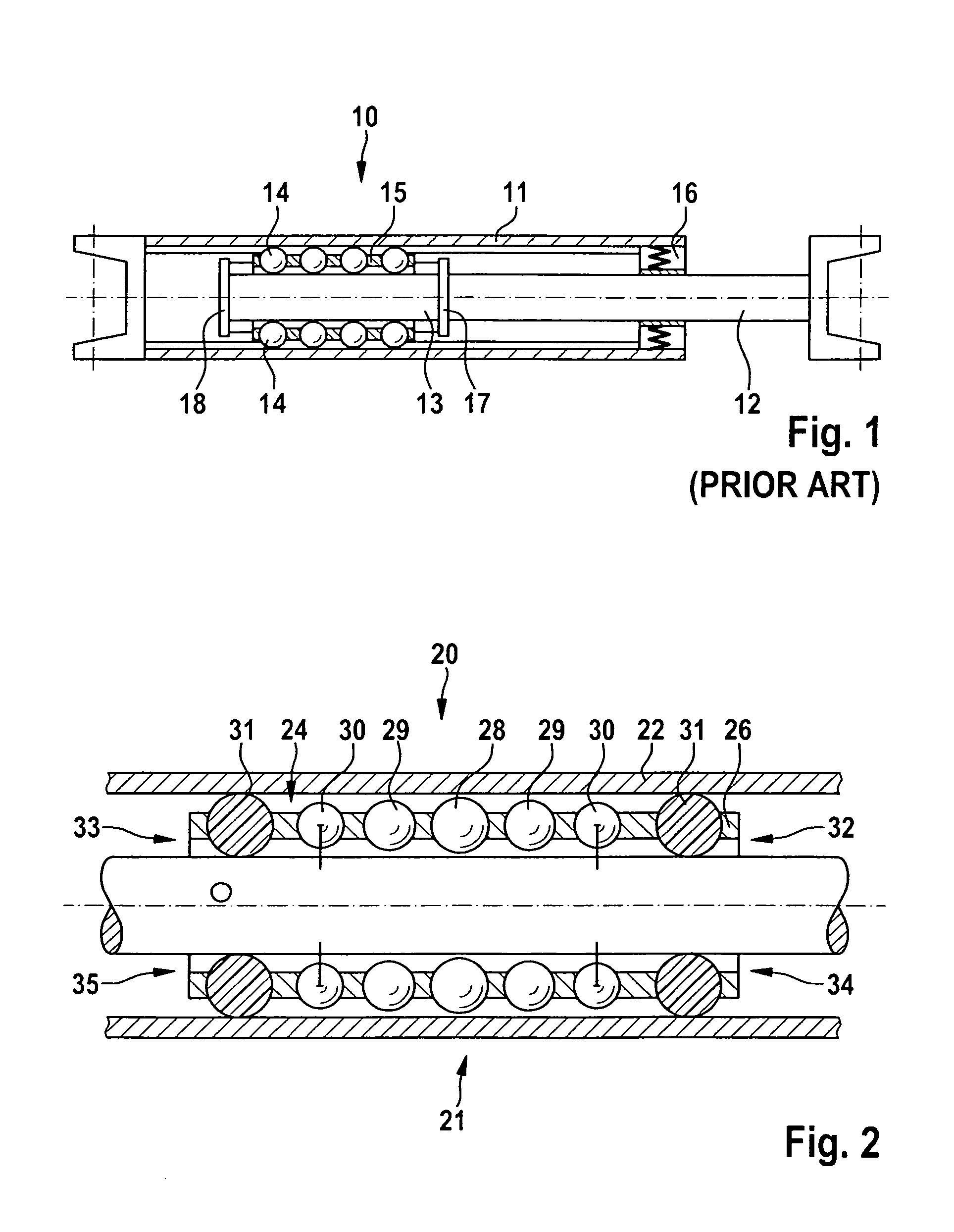
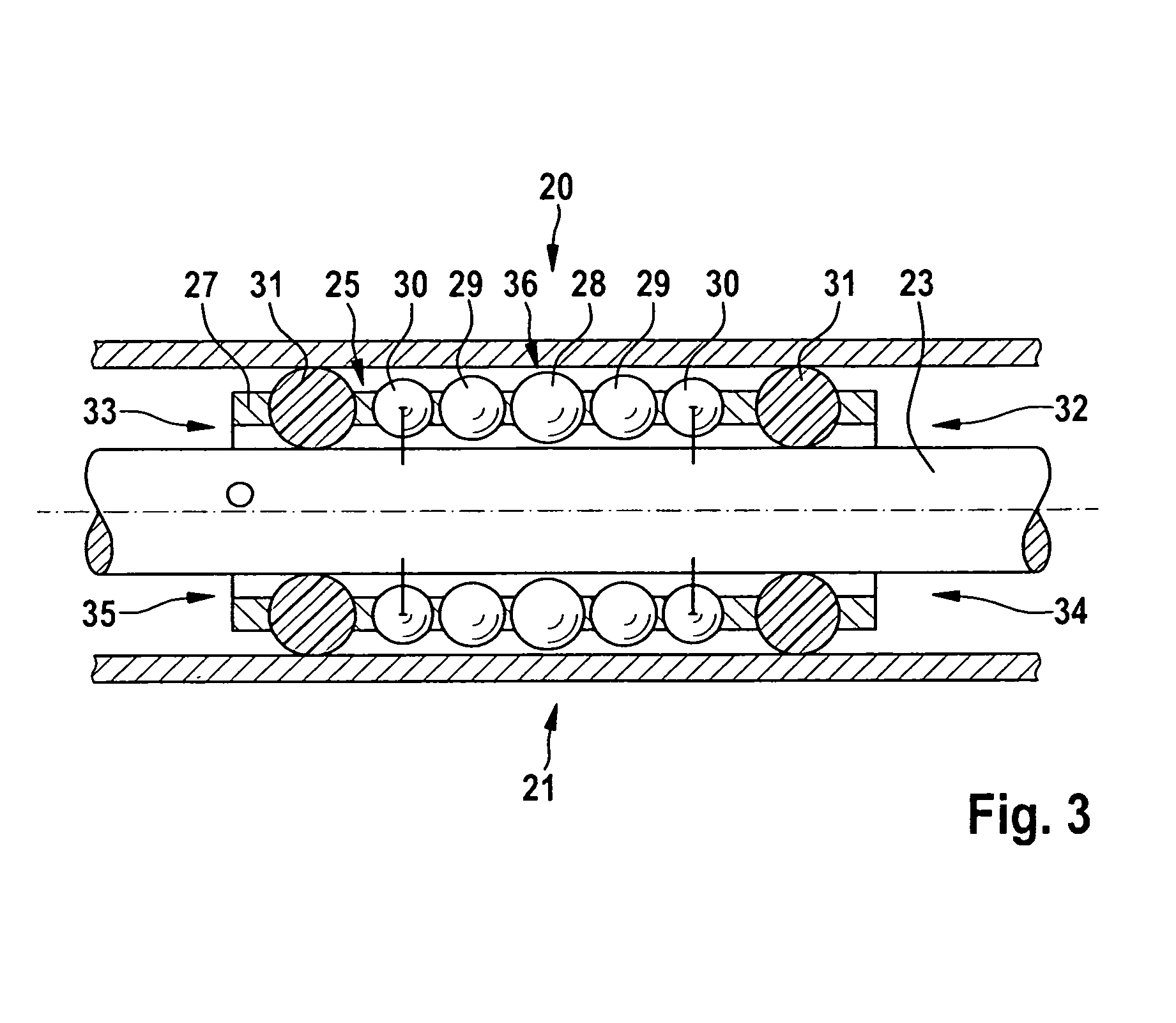
This patent is about a steering shaft design for vehicles that reduces the risk of vibrations being transmitted to the steering wheel, even in the event of an inclined position of the inner shaft. The design achieves this by using metallic rolling elements with decreasing diameters from the center of the rolling bearing toward the end faces, with multiple mutually adjacent metallic rolling elements having identical or different diameters. The rolling elements are mounted in an axially displaceable cage and can be seated against both the hollow shaft and the inner shaft, with a gap between them to prevent the transmission of vibrations. The design also includes the use of plastic material for certain rolling elements to damp vibrations and protect them from damage, as well as improve damping behavior. Overall, the design reduces the risk of vibration transmission and improves steering performance.

Problems solved by technology

The use of internal combustion engines having high compression causes the steering shaft known from the prior art to vibrate, which is undesirably perceived on the steering wheel, especially when driving straight ahead and at the beginning of a steering motion.
Various solutions using an air gap between an elastomer part and the inner shaft have not been able to effectively solve this problem.

Method used


Image

  • Steering shaft
  • Steering shaft
  • Steering shaft

Examples


Embodiment Construction

[0020]FIG. 1 shows a steering shaft 10 which is known from the prior art and has a hollow tube 11 and an inner shaft 12. The inner shaft 12 is mounted in the hollow shaft so as to be displaceable in the axial direction by way of a rolling bearing 13. The rolling bearing 13 has rolling elements 14 disposed in multiple rows behind each other in the axial direction. In the present case, the rolling elements 14 are designed as spheres having the same diameter, and are disposed in an axially displaceable cage 15. The axial displaceability of the cage 15 is limited by stops 17 and 18 provided on the inner shaft 12. The rolling elements 14 are used to transmit a torque, which is introduced via a steering wheel that is not shown in detail here, from the hollow shaft 11 to the inner shaft 12, or vice versa, and thus to wheels, which likewise are not shown here. An elastic bearing bushing 16 is intended to prevent vibrations, which originate in particular from an internal combustion engine, f...


PUM


Abstract

A steering shaft for a steering system of a motor vehicle, comprises an inner shaft mounted axially displaceably in a hollow shaft, wherein a rolling bearing having multiple metallic rolling elements, which are disposed axially in at least two rows, is disposed between the hollow shaft and the inner shaft. Previously known steering shafts cannot reliably present vibrations from being transmitted from the inner shaft to the hollow shaft. Therefore, the diameters of the metallic rolling elements decreases proceeding from the center of the rolling bearing toward the end faces thereof, wherein multiple mutually adjacent metallic rolling elements have identical and / or different diameters.

Description

BACKGROUND OF THE INVENTION[0001]The invention relates to a steering shaft, in particular for a steering system of a motor vehicle, comprising an inner shaft mounted axially displaceably in a hollow shaft, wherein a rolling bearing having multiple metallic rolling elements, which are disposed axially in at least two rows, is disposed between the hollow shaft and the inner shaft.[0002]The use of internal combustion engines having high compression causes the steering shaft known from the prior art to vibrate, which is undesirably perceived on the steering wheel, especially when driving straight ahead and at the beginning of a steering motion. Various solutions using an air gap between an elastomer part and the inner shaft have not been able to effectively solve this problem. An air gap between the rolling bearing, which is equipped with rolling elements having identical diameters, and the hollow shaft has likewise not proven to be of value.[0003]It is the object of the invention to im...

Claims


Application Information

Patent Timeline
Patent Type & Authority Patents(United States)
IPC IPC(8): F16C3/035B62D1/20B62D1/185B62D7/22F16C29/04F16D3/06
CPCB62D1/185B62D1/20B62D7/224F16C3/035F16C29/04F16D3/065F16C2326/24F16C29/002F16C33/32F16C2240/70
Inventor LINDE, JOACHIMFUCHS, VOLKER
Owner ROBERT BOSCH AUTOMOTIVE STEERING
Learn More