[0010]Therefore, a need has arisen for a liquid supply device, an image printing apparatus, and a liquid container, which overcome these and other shortcomings of the related art. Also, there is a demand for cost reduction of image printing apparatuses, and therefore it is desirable that the structure for preventing an ink cartridge from
jumping out of a mounting portion is simple at low cost. A technical
advantage of the invention is that the likelihood that a liquid container jumps out of a mounting portion is reduced, and the liquid container is relatively smoothly inserted into the mounting portion, with a simple and low-
cost structure.
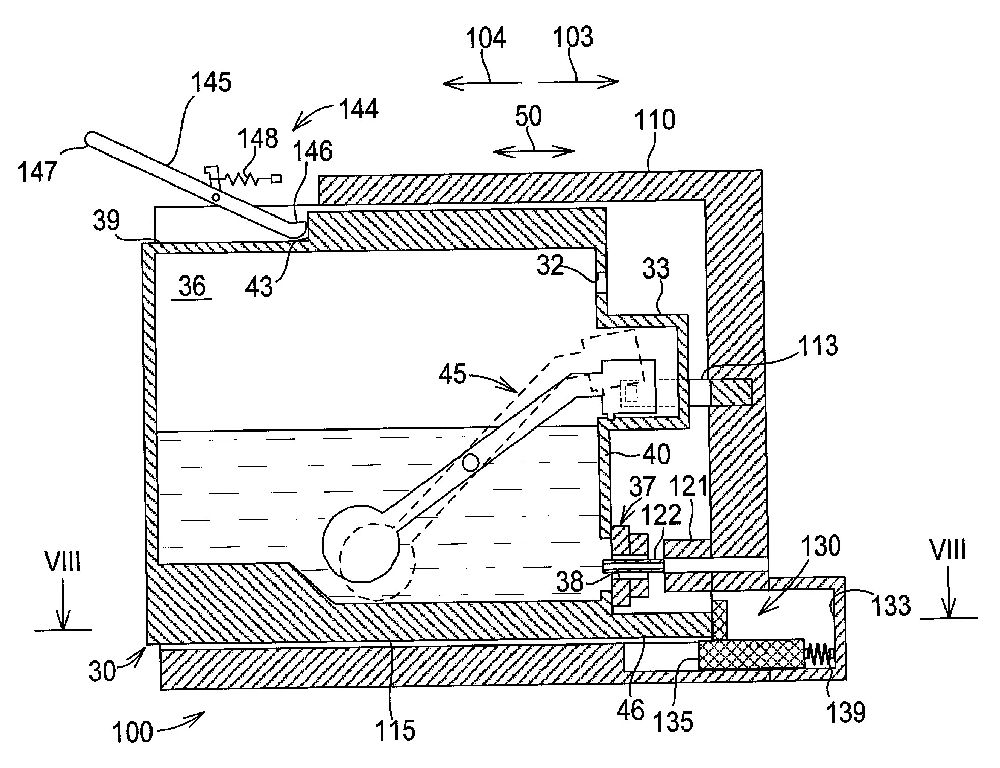
[0011]In an embodiment of the invention, a liquid supply device comprises a liquid container comprising a liquid chamber configured to store liquid therein and at least one contact portion. The liquid supply device also comprises a mounting portion having an opening, a first surface, and a second surface opposite the first surface, wherein the liquid container is configured to be inserted into the mounting portion in an insertion direction via the opening and to be removed from the mounting portion in a removal direction opposite the insertion direction via the opening. The mounting portion comprises an urging member configured to urge the liquid container positioned in the mounting portion toward the opening, at least one stopper comprising a resilient member extending from at least one of the first surface and the second surface in a direction intersecting the insertion direction, wherein the resilient member is bendably deformable in both the insertion direction and the removal direction, and wherein the resilient member is configured to contact the at least one contact portion when the liquid container is inserted into and removed from the mounting portion, and a retaining member configured to selectively retain the liquid container in the mounting portion against an urging force of the urging member. When the liquid container is mounted in the mounting portion, the at least one contact portion faces the at least one of the first surface and the second surface from which the resilient member of the at least one stopper extends, and the resilient member is configured such that a first force required for deforming the resilient member in the insertion direction is less than a second force required for deforming the resilient member in the removal direction.
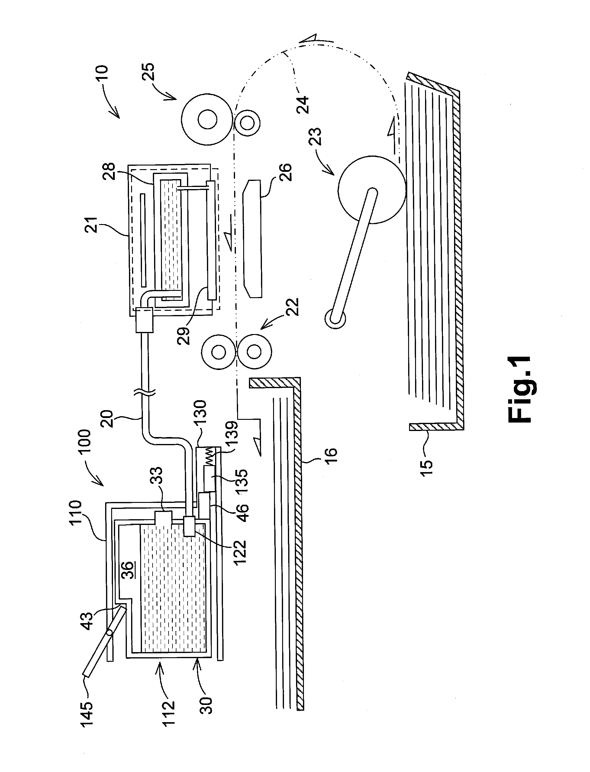
[0012]In another embodiment of the invention, an image printing apparatus comprises a liquid supply device. The liquid supply device comprises a liquid container comprising a liquid chamber configured to store liquid therein, and at least one contact portion. The liquid supply device also comprises a mounting portion having an opening, a first surface, and a second surface opposite the first surface, wherein the liquid container is configured to be inserted into the mounting portion in an insertion direction via the opening and to be removed from the mounting portion in a removal direction opposite the insertion direction via the opening. The mounting portion comprises an urging member configured to urge the liquid container positioned in the mounting portion toward the opening, at least one stopper comprising a resilient member extending from at least one of the first surface and the second surface in a direction intersecting the insertion direction, wherein the resilient member is bendably deformable in both the insertion direction and the removal direction, and wherein the resilient member is configured to contact the at least one contact portion when the liquid container is inserted into and removed from the mounting portion, and a retaining member configured to selectively retain the liquid container in the mounting portion against an urging force of the urging member. The image printing apparatus also comprises a printing portion configured to selectively eject liquid supplied from the liquid supply device. When the liquid container is mounted in the mounting portion, the at least one contact portion faces the at least one of the first surface and the second surface from which the resilient member of the at least one stopper extends, and the resilient member is configured such that a first force required for deforming the resilient member in the insertion direction is less than a second force required for deforming the resilient member in the removal direction.
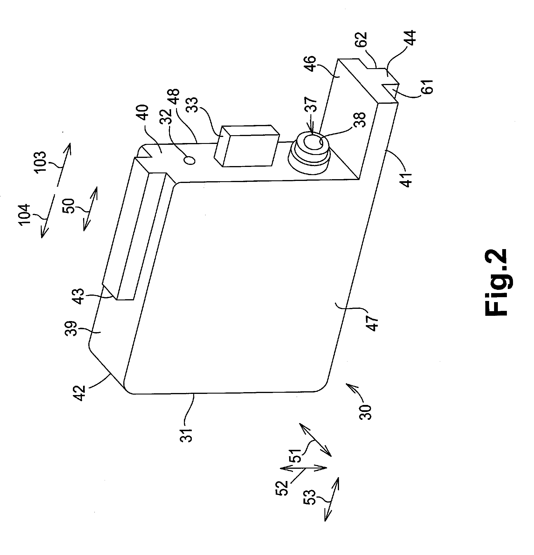
[0013]In yet another embodiment of the invention, a liquid container is configured to be removably inserted into a mounting portion in an insertion direction via an opening, and to be removed in a removal direction opposite the insertion direction. The liquid container comprises a liquid chamber configured to store liquid therein, at least one container surface configured to face at least one of a first surface and a second surface opposite the first surface of the mounting portion, and at least one container protrusion extending from the at least one container surface, wherein when the liquid container is inserted into the mounting portion and when the liquid container is removed from the mounting portion, the at least one container protrusion is configured to contact and deform a deformable resilient member extending from at least one of the first surface and the second surface of the mounting portion in a direction intersecting the insertion direction, wherein the at least one container protrusion is configured to exert a first force required for the container protrusion to deform the resilient member in the insertion direction when the liquid container is inserted into the mounting portion, and to exert a second force for deforming the resilient member in the removal direction when the liquid container is removed from the mounting portion, wherein the first force is less than the second force.

