Intraocular lens injector

a technology of injector and intraocular lens, which is applied in the field of intraocular lens injector, can solve the problems of increasing the difficulty of surgery, inconvenient connection of the cartridge and the cylinder for the use of the intraocular lens injector, and blindness in severe cases, and achieves the effect of convenient removal of the cover and easy detachability

Active Publication Date: 2011-12-22
RET
View PDF1 Cites 11 Cited by
  • Summary
  • Abstract
  • Description
  • Claims
  • Application Information

AI Technical Summary

Benefits of technology

[0016]The inclined portion may have a width smaller than that of the slide portion to be easily detachable.
[0017]The inclined portion may include an upwardly bent portion at the end thereof and is connected to a base end of the first receiving groove in a reclining manner so as to facilitate the removal of the cover member having the inclined portion when the first wing portion having the first receiving groove is inwardly folded.

Problems solved by technology

Cataract is a disease caused by opacity of the crystalline lens of the eye and may lead to blindness in severe cases.
The above-described intraocular lens injector has a structure in which a cartridge in which an intraocular lens in a folded or rolled state is placed and a cylinder for pushing the intraocular placed in the cartridge to the eye are separated from each other, and thus it is inconvenient to connect the cartridge and the cylinder for the use of the intraocular lens injector.
Moreover, the intraocular lens preloaded into the cartridge is inserted into the eye by pushing the cylinder during cataract surgery on the eye from which the crystalline eye is extracted, which increases the difficulty of the surgery.
Various studies have been carried out to solve the above problems, various studies have been conducted to in progress in recently years, but there is no clear solution yet.

Method used


Image

  • Intraocular lens injector
  • Intraocular lens injector
  • Intraocular lens injector

Examples


Embodiment Construction

[0023]Hereinafter, exemplary embodiments of the present invention will be described in detail below with reference to the accompanying drawings such that those skilled in the art to which the present invention pertains can easily practice the present invention.

[0024]The configuration of an intraocular lens injector of the present invention will be described below.

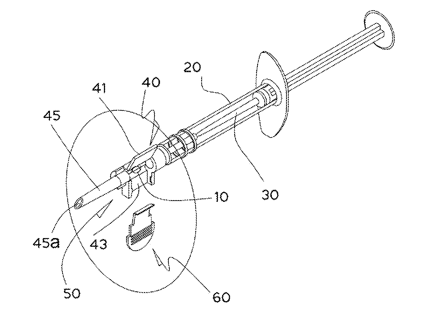
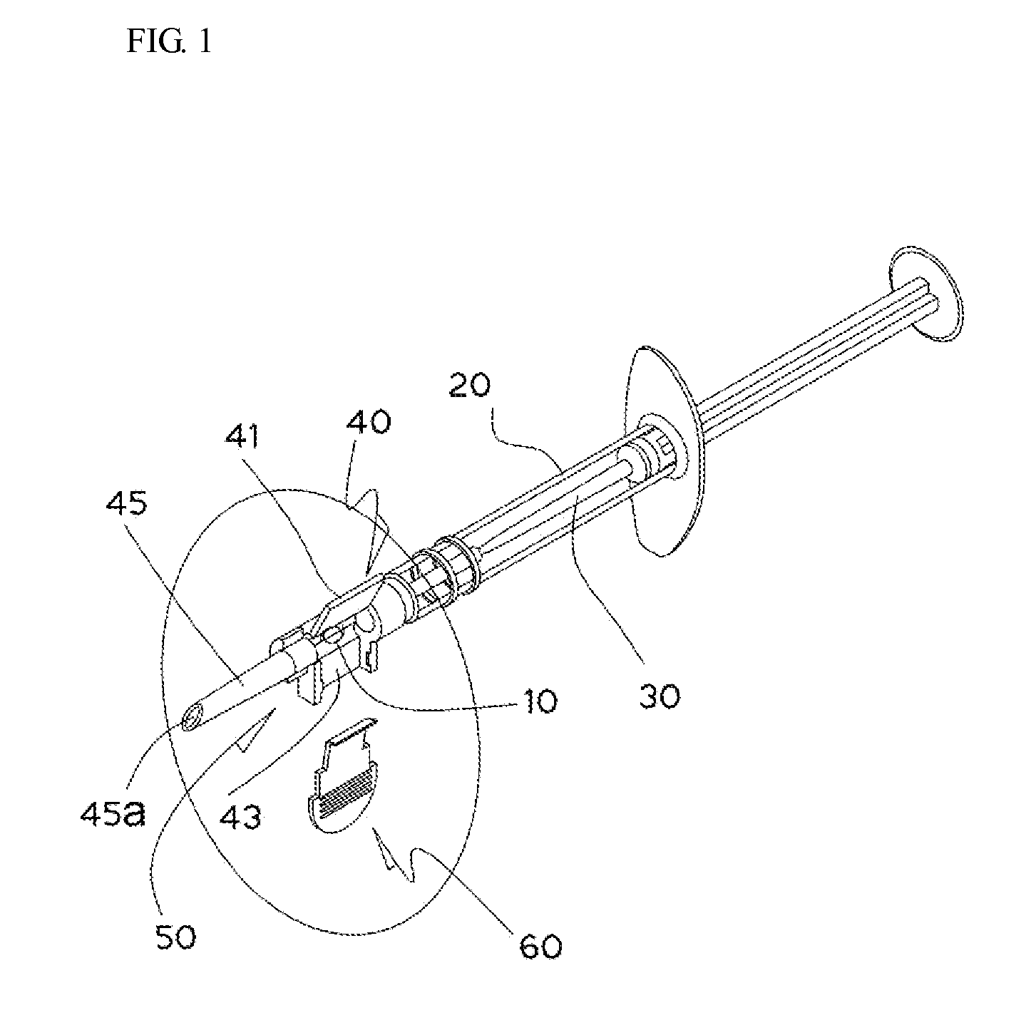
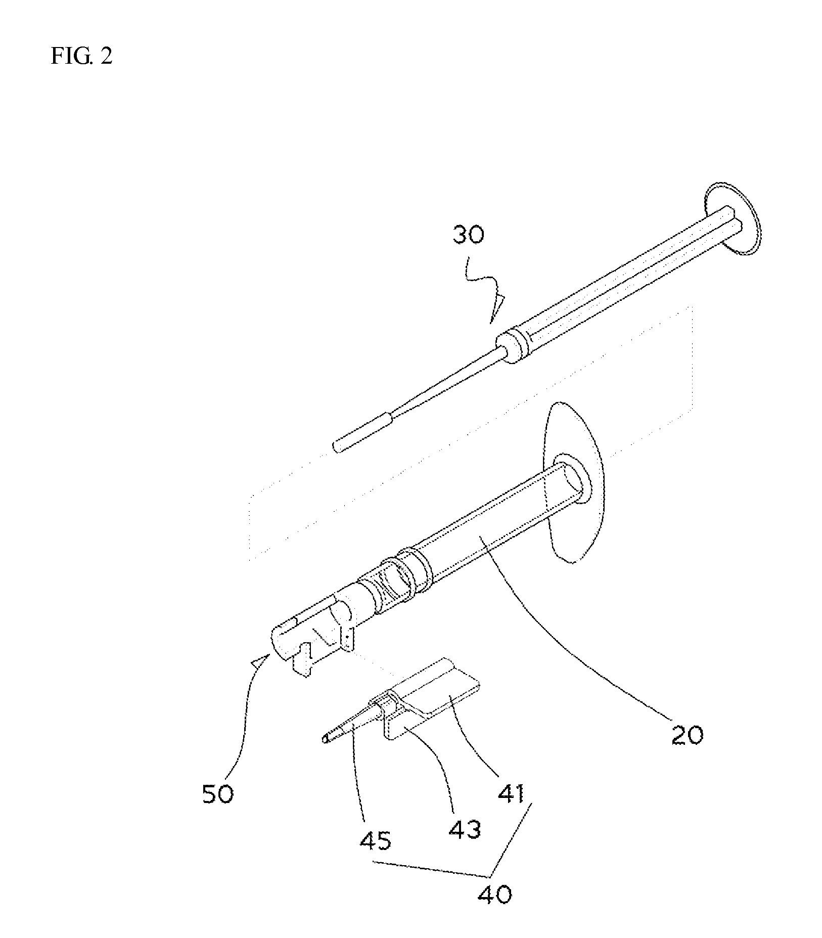
[0025]The intraocular lens injector for inserting an intraocular lens 10 into an eye of the present invention includes: a cylindrical cylinder 20, into which a plunger 30 for passing the intraocular lens 10 to be guided into the eye is inserted; a connection block 50 having a C-shaped longitudinal cross-section and integrally formed at the front end of the cylinder 20; a cartridge 40, which is connected to the connection block 50 and includes first and second wing portions 41 and 43, which are folded with respect to each other, first and second receiving grooves 41a and 43a formed at the connection portion of the first and ...


PUM


Abstract

Disclosed herein is an intraocular lens injector for inserting an intraocular lens into an eye, the intraocular lens injector including: a cylindrical cylinder, into which a plunger for passing the intraocular lens to be guided into the eye is inserted; a connection block having a C-shaped longitudinal cross-section and integrally formed at the front end of the cylinder; a cartridge, which is connected to the connection block and includes first and second wing portions, which are folded with respect to each other, first and second receiving grooves formed at the connection portion of the first and second wing portions and having a semicircular longitudinal cross-section, and a truncated conical guide portion, which extends from the second receiving groove in the lateral direction and includes a guide passage having a circular cross-section corresponding to the shape of the assembled first and second receiving grooves; and a cover member inserted into the connection block together with the second wing portion 43 of the cartridge 40 and detachably connected to the connection block.

Description

CROSS-REFERENCE TO RELATED APPLICATION[0001]This application claims priority to and the benefit of Korean Patent Application No. 10-2010-0057056, filed on Jun. 16, 2010, the disclosure of which is incorporated herein by reference in its entirety.BACKGROUND[0002]1. Field of the Invention[0003]The present invention relates to an intraocular lens injector for inserting an intraocular lens into an eye in replacement of a crystalline lens extracted during cataract surgery, and more particularly, to an intraocular lens injector, in which a cartridge, in which an intraocular lens is placed, is integrally formed with a cylinder, in which a plunger slides, and the cartridge is slidably covered such that the intraocular lens can be kept or carried while being placed in the cartridge, thereby eliminating the inconvenience of connecting the cartridge including the intraocular lens to the cylinder during cataract surgery and facilitating the cataract surgery.[0004]2. Discussion of Related Art[00...

Claims


Application Information

Patent Timeline
Patent Type & Authority Applications(United States)
IPC IPC(8): A61F9/007
CPCA61F2/1678
Inventor HAN, MYOUNG SOO
Owner RET
Why Eureka
Try Eureka