Vitreous Compressing Plate Haptic

a technology of haptic and vitreous, which is applied in the field of vitreous compressing plate haptic, can solve the problems of limited response of the lens optic of a traditional plate haptic lens, and achieve the effects of reducing the incidence and complication of “z” formation, enhancing the effect of pressure changes within the eye, and increasing the contact area

Active Publication Date: 2011-12-22
CUMMING JAMES STUART
View PDF14 Cites 25 Cited by
  • Summary
  • Abstract
  • Description
  • Claims
  • Application Information

AI Technical Summary

Benefits of technology

[0013]By extending the lateral surface area of the plates adjacent the optic to partially surround the optic, the haptic presses posteriorly on the vitreous immediately adjacent to and almost surrounding the lens optic. The extended part of the plate increases the area of contact of the plate haptic with the vitreous face, on either side of the optic and enhances the effect of the pressure changes within the eye that occur naturally with constriction and relaxation of the ciliary muscle that occurs with accommodation.
[0014]A second feature of this plate design is a small triangular extension of distal-lateral ends of the plate haptics, thereby widening the distal end of the plate haptic by 0.75-1.5 mm on either side of each plate haptic. This allows for a greater area of contact between the fibrosed capsule and the tip of the plates to reduce the incidence and complication of “Z” formations.

Problems solved by technology

This was just one of the complications of this first design.
However, due to its construction, the lens optic of a traditional plate haptic lens is limited in its response to the change in vitreous pressure.

Method used


Image

  • Vitreous Compressing Plate Haptic
  • Vitreous Compressing Plate Haptic
  • Vitreous Compressing Plate Haptic

Examples


Embodiment Construction

[0021]The above described drawing figures illustrate the described invention and method of use in at least one of its preferred, best mode embodiment, which is further defined in detail in the following description. Those having ordinary skill in the art may be able to make alterations and modifications to what is described herein without departing from its spirit and scope. Therefore, it should be understood that what is illustrated is set forth only for the purposes of example and should not be taken as a limitation on the scope of the present apparatus and its method of use.

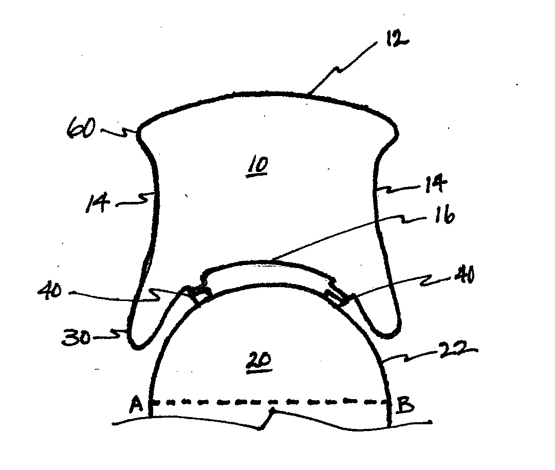
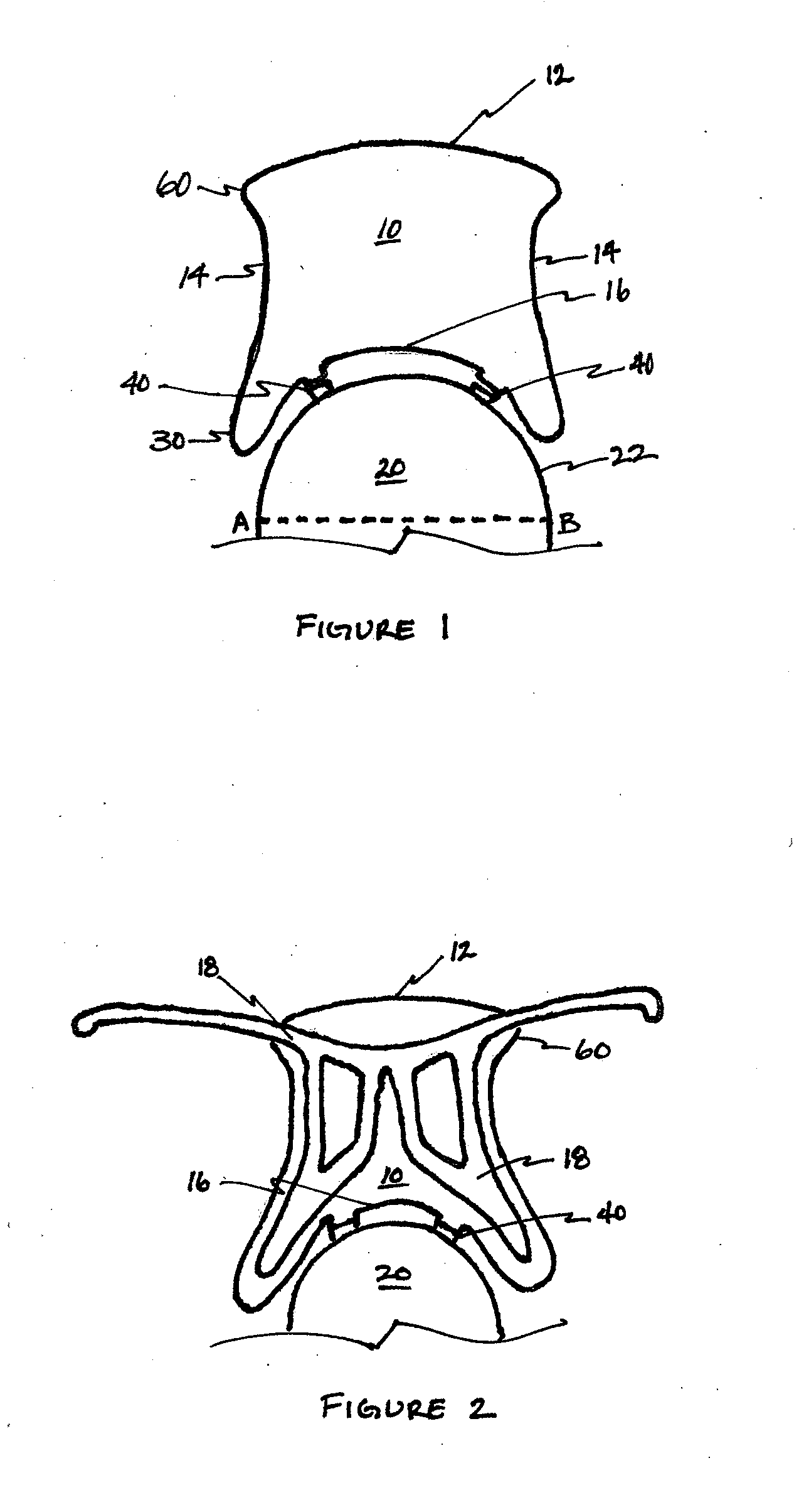
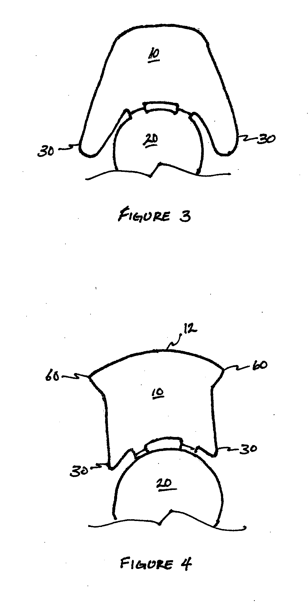
[0022]As illustrated in FIG. 1, an intraocular accommodating lens may comprise at least one plate haptic 10 and a lens optic 20.

[0023]The plate haptic 10 may comprise a distal portion 12, opposing lateral portions 14, and a proximal portion 16. In at least one preferred embodiment, the plate haptic 10 may be substantially or partially constructed of flexible material, such as silicone, acrylic, hydrogel, and / o...


PUM


Abstract

A plate haptic is used with an intraocular lens optic displaceable in response to vitreous pressure changes. The plate haptic comprises: a plurality of opposing lateral portions; a distal portion having a plurality of opposing projections extending substantially laterally therefrom; and a proximal portion comprising a strap across which is a hinge connecting the lens optic to the haptic. The intersection of the proximal portion with each lateral portion forms a plurality of appendages, or paddles, to partially surround the optic. The appendages, projections, and hinged straps combine to substantially aid displacement of the lens optic in response to changes in vitreous pressure.

Description

CROSS-REFERENCE TO RELATED APPLICATIONS[0001]This application is based on and claims the benefit of the filing of U.S. Provisional Patent Application No. 61 / 398,107, filed Jun. 21, 2010; U.S. Provisional Patent Application No. 61 / 398,098, filed Jun. 21, 2010; U.S. Provisional Patent Application No. 61 / 398,115, filed Jun. 21, 2010; and U.S. Provisional Patent Application No. 61 / 398,099, filed Jun. 21, 2010, the contents and disclosure of which are fully incorporated herein by reference.[0002]This application is related to U.S. Non-Provisional Patent Application No. 13 / 017,189, filed Feb. 14, 2011, the contents and disclosure of which is fully incorporated herein by reference.BACKGROUND OF THE INVENTION[0003]Accommodating Intraocular Lenses were developed in the early 1900's and have been sold in Europe for the last ten years and later in the U.S. They function by means of forward movement of the optic upon constriction of the ciliary muscle which increases the pressure in the posteri...

Claims


Application Information

Patent Timeline
Patent Type & Authority Applications(United States)
IPC IPC(8): A61F2/16
CPCA61F2/1613A61F2/1624A61F2002/1689A61F2002/1683A61F2002/1682A61F2220/0091A61F2250/0018A61F2/1629A61F2002/169A61F2002/16905A61F2002/1681A61F2230/0006A61F2230/0069A61F2/16
Inventor CUMMING, JAMES STUART
Owner CUMMING JAMES STUART
Why Eureka
Try Eureka