
System and method for flowing fluids through electronic chassis modules

a technology of electronic chassis and fluid distribution system, which is applied in the field of fluid distribution, can solve the problems of insufficient adoption of direct liquid cooling in practice, high risk of liquid leakage and spillage reaching the electronic circuit, and insufficient service of such a system

Inactive Publication Date: 2011-12-22
NICEWONGER MARK RANDAL
View PDF0 Cites 142 Cited by
  • Summary
  • Abstract
  • Description
  • Claims
  • Application Information

AI Technical Summary

Benefits of technology

[0014]c. localize the leak to prevent spilled coolant from unduly affecting the bulk of equipment in the rack,
[0015]d. provide a means of safely removing spilled coolant from the rack before it can reach surrounding equipment.

Problems solved by technology

However, direct liquid cooling has not been widely adopted in practice, largely due to difficulties encountered in the mechanics of delivering liquids to the great number of circuits often packed within the constrained space of an equipment rack.
Even when the flexible tubing is equipped on at least one end with a quick-disconnect type of fitting, servicing such a system can be difficult, and the risk of liquid leaks and spills reaching the electronic circuits is considered too high for adoption in most applications.
A leak or spill at a single point could jeopardize the operation of the entire rack of eighty-four servers.

Method used


Image

  • System and method for flowing fluids through electronic chassis modules
  • System and method for flowing fluids through electronic chassis modules
  • System and method for flowing fluids through electronic chassis modules

Examples


Embodiment Construction

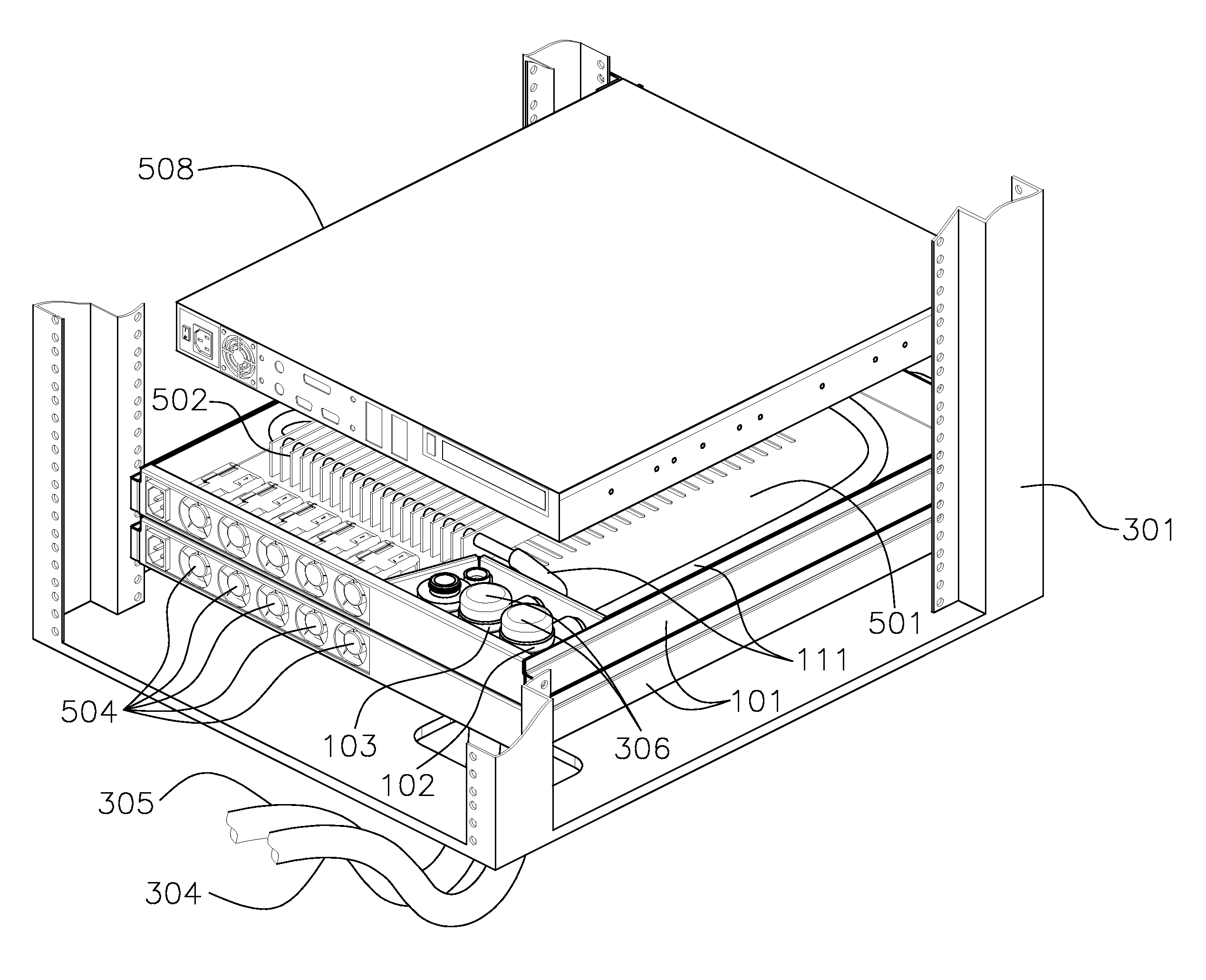
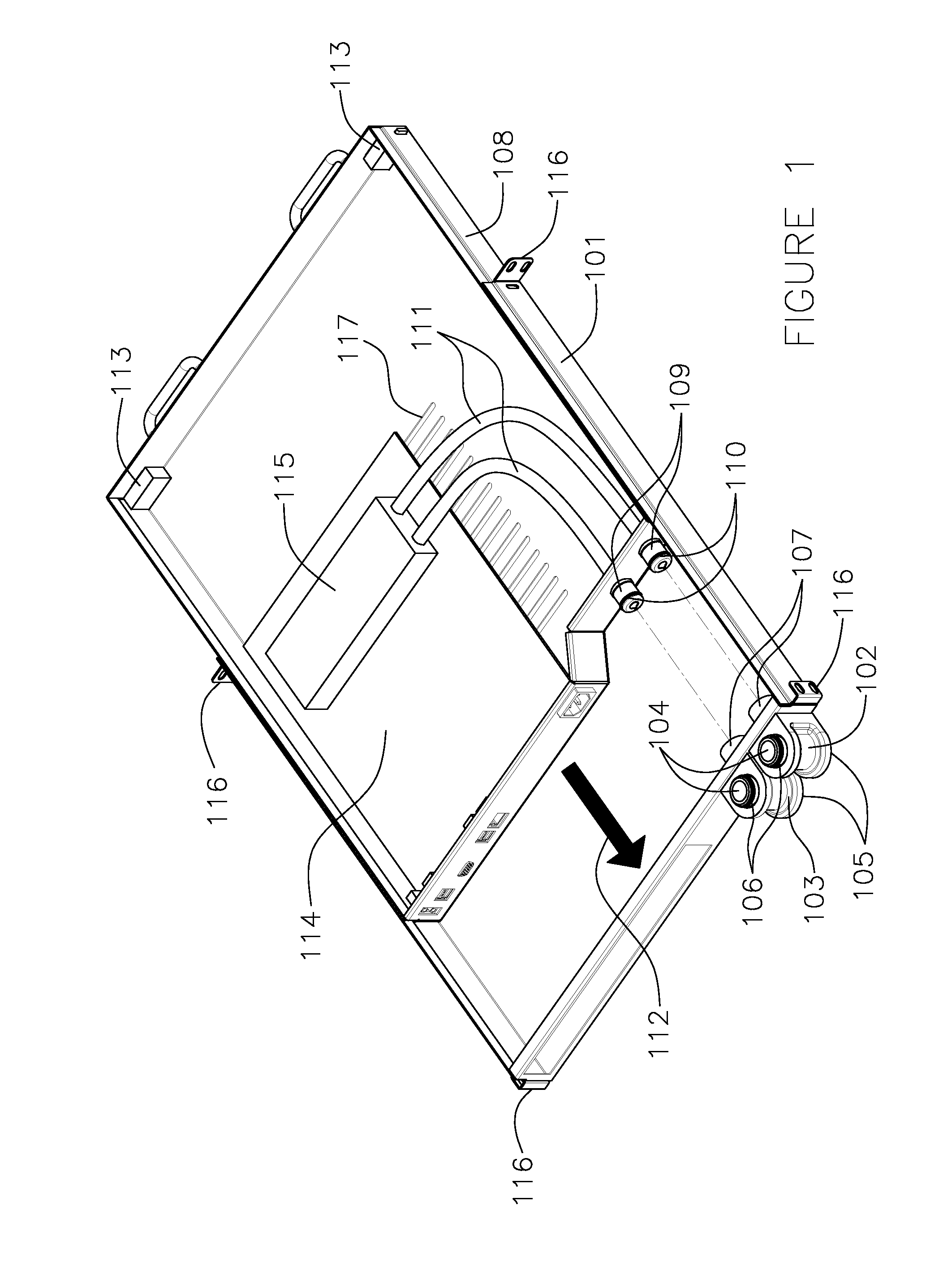
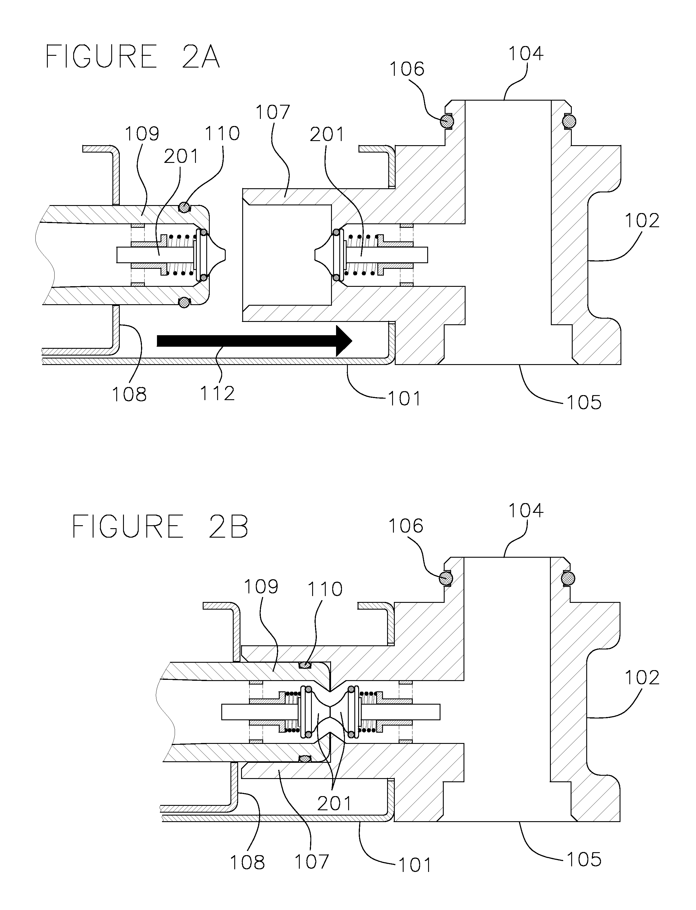
[0031]A preferred embodiment of the invention would be for the purpose of cooling servers, where each server module is individually housed in a chassis having a 1U form. The chassis provides a coolant loop for cooling the server CPU and other electronic components such as communications or data storage devices within the module. The chassis can alternately house heat exchanger modules for transferring heat between coolant loops, or airborne heat to a coolant loop. The coolant in this embodiment is a liquid, or in alternate embodiments the module may implement a two-phase cooling system where the coolant entering the module is a liquid and the coolant exiting is a gas, or mixture of gas and liquid. Multiple coolant loops can be implemented with differing coolants employed for each loop. Multiple chassis are placed into a standard 19-inch equipment rack, with the liquid coolant loop interflowing between adjoining chassis.

[0032]FIG. 1 illustrates a rear view of one such embodiment, wit...


PUM


Abstract

An electronic chassis distributes fluids to adjacent chassis and electronic modules housed within the chassis. Provision is made for the detection, containment, and removal of liquid spilled within the chassis. The fluids may be used as coolants, and provision is made for heat exchanger modules to be included within the chassis. Provision is further made to include fluid sensors and actuators, allowing for monitoring and control of fluid distribution by a controller.

Description

CROSS-REFERENCE TO RELATED APPLICATIONS[0001]This application claims priority to: 1) United States provisional application, Ser. No. 61 / 356,016, filed Jun. 17, 2010, which application(s) are all also incorporated by reference herein in their entirety.FIELD OF TECHNOLOGY[0002]This disclosure relates generally to the technical fields of routing fluids, and in one example embodiment, this disclosure relates to a method, apparatus and system of distributing fluids through interchangeable modules.BACKGROUND[0003]1. Technical Field[0004]The present invention relates to the distribution of fluids to electronic equipment. Such equipment generally includes computers, communications equipment, and data storage devices. The electronic circuits of such equipment are typically housed either directly within a chassis, or within a second sub-chassis module fitting into a main chassis. The chassis are often mounted into an equipment rack, the standard 19-inch rack being commonly employed. Fluids di...

Claims


Application Information

Patent Timeline
IPC IPC(8): G05D7/06G05D23/19F15D1/00H05K7/20
CPCF28D15/00F28F2250/08H05K7/20781Y10T137/6851Y10T137/0402
Inventor NICEWONGER, MARK RANDAL
Owner NICEWONGER MARK RANDAL
Learn More