Cleaner for Medical Device

a technology for cleaning devices and medical devices, applied in the field of medical devices, can solve the problems of requiring cleaning and decontamination of the end of the luer connector, exposing the connector to debris and contamination,

Inactive Publication Date: 2011-12-29
MEDICAL COMPONENTS INC
View PDF25 Cites 100 Cited by
  • Summary
  • Abstract
  • Description
  • Claims
  • Application Information

AI Technical Summary

Benefits of technology

[0007]Briefly, the present invention is a cleaner assembly having a housing defining a device-receiving cavity open at a first end and extending to a transverse bottom forming a closed second end. One or more scrubbing components are affixed within the cavity containing scrubbing portions that engage surfaces of the medical device inserted into the cavity thereby scrubbing them upon manipulation of the medical device, or manipulation of the cleaner assembly with respect to the medical device. The housing is preferably cup-shaped, and preferably, a cover is affixed across the open first end of the cup housing to seal the interior, which cover is peelable from the cup when desired to clean a medical device. Such a cover could be of a semi-permeable material permitting sterilization of the cleaner assembly upon completion of manufacturing.

Problems solved by technology

Of course, when unconnected to the fluid lines, the ends of the luer connectors are exposed to debris and contamination and require cleaning and decontamination prior to each connection.

Method used


Image

  • Cleaner for Medical Device
  • Cleaner for Medical Device
  • Cleaner for Medical Device

Examples


first embodiment

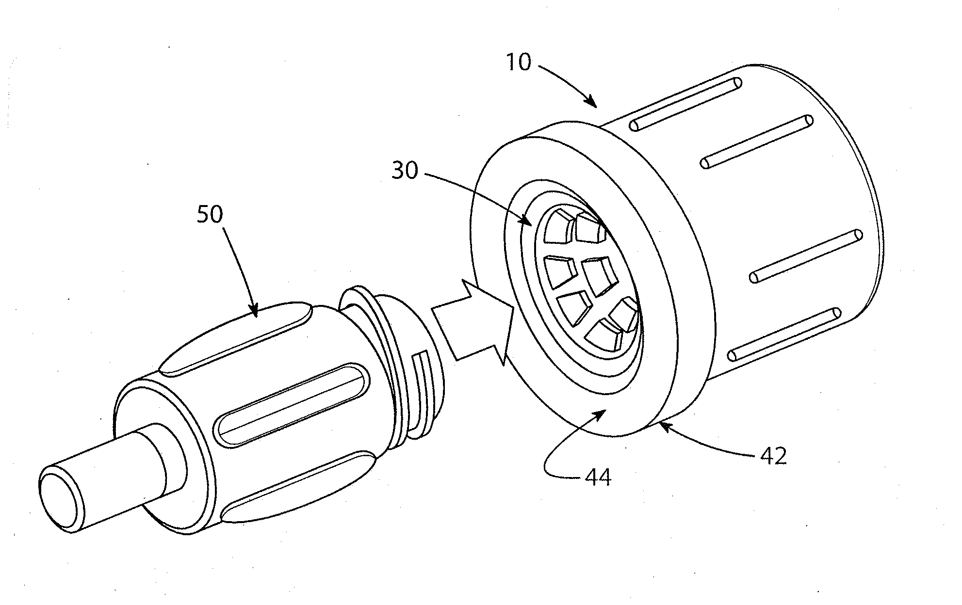
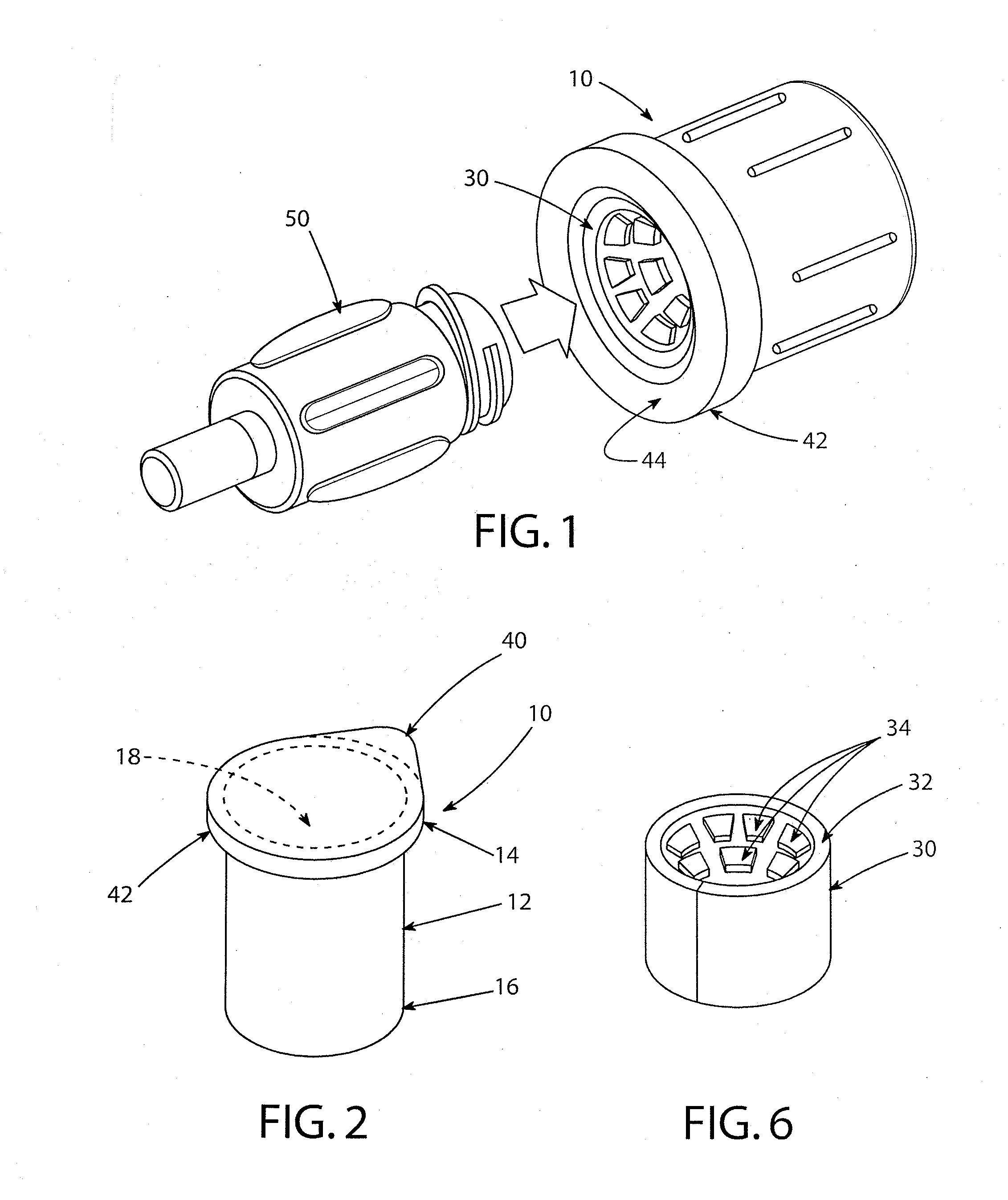
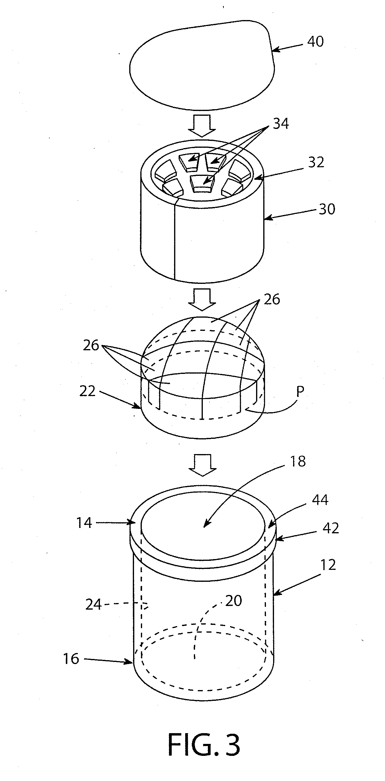
[0027]Second scrubber component 30 is depicted in FIGS. 3 to 7 in a It may preferably be formed of an integral or one-piece rectangular body 32 that is generally flat and rather thin, as seen in FIG. 7, and which is then curled up and installed within the housing 12 down to the proximal end of first scrubber component 22 to extend circumferentially around the cavity proximate the proximal housing end 14, such as by use of a bonding agent such as LOCTITE (trademark of Henkle North America) cyanoacrylate or other acrylic adhesive, or an epoxy adhesive. Second scrubber component 30 defines an array of flexible projections 34 that upon installation in the housing, project radially inwardly. Adjacent the body 32, the flexible projections may have any suitable configuration or shape such as a rectangular cross-section as shown, and the projections may vary in length within the same array. The end portions of the flexible projections 34 will engage the exterior surfaces of the end portion...

second embodiment

[0028]Flexible projections 34 of second scrubber component 30 may be blunt-ended as shown in FIGS. 3 to 7, or, as is seen in FIG. 8 in a second embodiment, the flexible projections 36 of component 30′ may be point-shaped; both shapes may be used in the same array, as well as any other suitable shape or configuration. The end portions of the flexible projections 34,36 will engage the exterior surfaces of the end portion of a medical device inserted into the device-receiving cavity 18 for scrubbing the device end portion. Antimicrobial fluid initially absorbed into the first scrubber component 22 would be expressed therefrom upon insertion of the medical device end portion into the cavity thus compressing the foam material thereof, and the fluid would flow along the second scrubber component and its flexible projections, and the medical device itself, to the exterior surfaces thereof. Materials for the second scrubber component 30 include silicone elastomer, polyurethane, polypropylen...


PUM


Abstract

A cleaner assembly (10) for cleaning a medical device such as a luer connector. The assembly includes a cup-shaped housing (12) having a cavity (18) extending from an open first end (14) to a closed second end (16), and a first scrubber (22) affixed at the bottom and along side surfaces of the cavity (18) and saturated with antimicrobial fluid. The first scrubber (22) includes compressible fingers (26) co-extending toward the open first end (14) engageable by the medical device end portion inserted into the cavity whereupon the fingers (26) scrub the exterior and interior surfaces of the end of the device and applying the antimicrobial fluid thereto by being compressed by the device end. A second scrubber (30,30′) is affixed to cavity side walls (32) adjacent the open first end and has flexible projections (34 or 36) extending radially inwardly to scrub exterior surfaces of the device upon insertion.

Description

CROSS-REFERENCE TO RELATED APPLICATIONS[0001]This application claims priority from U.S. Provisional Patent Application Ser. No. 61 / 357,730 filed Jun. 23, 2010.FIELD OF THE INVENTION[0002]This relates to the field of medical devices and more particularly to devices for cleaning and decontaminating a medical device such as a luer connector.BACKGROUND OF THE INVENTION[0003]In catheter assemblies such as are used in hemodialysis, proximal ends of the catheters are terminated in luer connectors that are disposed outside of the patient, and the luer connectors enable easy and rapid connection to respective fluid lines of the hemodialysis apparatus in a manner permitting easy and rapid disconnect. Of course, when unconnected to the fluid lines, the ends of the luer connectors are exposed to debris and contamination and require cleaning and decontamination prior to each connection. Prior art cleaner devices for medical and dental devices, generally, are set forth in U.S. Pat. Nos. 4,439,884...

Claims


Application Information

Patent Timeline
Patent Type & Authority Applications(United States)
IPC IPC(8): A46B15/00A46B9/00
CPCA61C19/002A61M39/165A61M39/162A61M39/16
Inventor SCHWEIKERT, TIMOTHY M.
Owner MEDICAL COMPONENTS INC
Why Eureka
Try Eureka