Mitigation of undesired electromagnetic radiation using passive elements

a technology of electromagnetic radiation and passive elements, applied in the direction of antennas, antenna details, antenna couplings, etc., can solve the problems of undesired negative effects of device transmitter operation, radiation emitted by such transmitters may pose a health risk to the user or other persons sufficiently close to the transmitter, radiation may interfere with the operation of nearby electronics or communication devices, etc., to achieve the effect of reducing undesired electromagnetic radiation

Active Publication Date: 2011-12-29
NETGEAR INC
View PDF4 Cites 11 Cited by
  • Summary
  • Abstract
  • Description
  • Claims
  • Application Information

AI Technical Summary

Benefits of technology

[0009]An object of the present invention is to provide a method and apparatus for mitigation of undesired portions of electromagnetic radiation associated with an antenna. In accordance with an aspect of the present invention, there is provided an apparatus for mitigating undesired portions of electromagnetic radiation (EMR) associated with an antenna, the apparatus comprising: a coupling element EM inductively coupled with the antenna, the coupling element being co-polarized with the antenna; and one or more dissipating elements EM inductively coupled with the coupling element, each of the one or more dissipating elements being differently polarized than the antenna.
[0010]In accordance with another aspect of the present invention, there is provided a communication device comprising an antenna and an apparatus for mitigating undesired portions of electromagnetic radiation (EMR) associated with the antenna, the apparatus comprising: a coupling element EM inductively coupled with the antenna, the coupling element being co-polarized with the antenna; and one or more dissipating elements EM inductively coupled with the coupling element, each of the one or more dissipating elements being differently polarized than the antenna.

Problems solved by technology

There is currently concern that exposure to electromagnetic radiation emitted by such transmitters may pose a health risk to the user or other persons sufficiently close to the transmitter.
Undesired electromagnetic radiation may also interfere with operation of nearby electronics or communication devices.
However, the above approaches may cause undesirable negative effects on device transmitter operation.
For example, mutual coupling between the metallic shield and the device antenna may negatively impact antenna operation.
These approaches represent broad or untargeted attempts to minimize exposure to electromagnetic radiation which may not be feasible in some cases.
However, this approach requires conversion of captured RF energy to a form usable by the device being operated, which may be complicated and inefficient.

Method used


Image

  • Mitigation of undesired electromagnetic radiation using passive elements
  • Mitigation of undesired electromagnetic radiation using passive elements
  • Mitigation of undesired electromagnetic radiation using passive elements

Examples


example 1

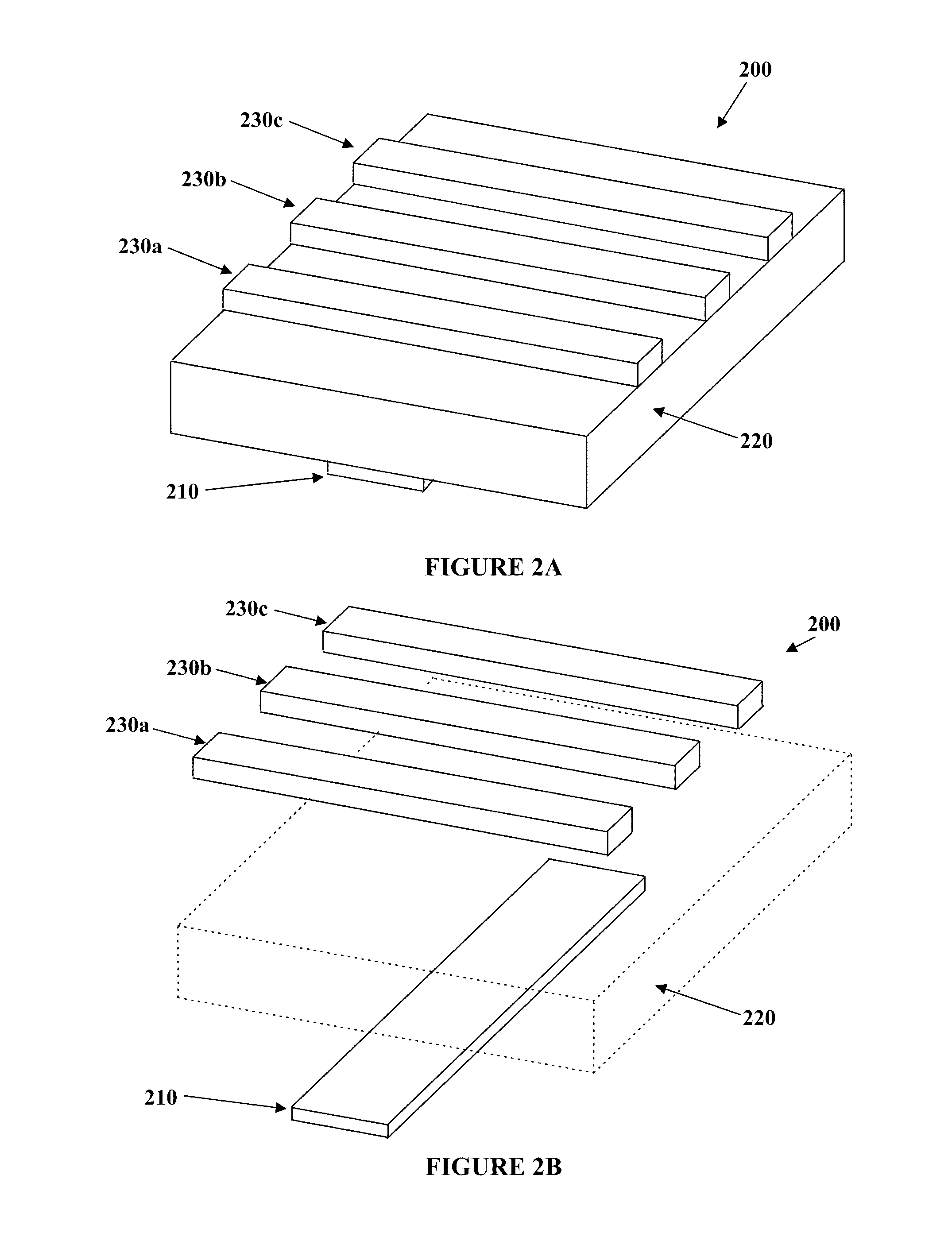
[0093]FIGS. 2A and 2B illustrate an apparatus 200 for mitigating undesired portions of electromagnetic radiation associated with an antenna in accordance with an embodiment of the present invention. FIG. 2B is an exploded view of FIG. 2A. The apparatus 200 comprises a coupler 210, an intermediate layer of insulating or dielectric material 220 and a plurality of dissipaters 230a, 230b, 230c. The coupler 210 is coupled to a first side of the intermediate layer 220, while the dissipaters 230a, 230b, 230c are coupled to a second side of the intermediate layer 220 opposite the first side.

[0094]The coupler 210 is a substantially rectangular strip of conductive material, such as copper, thin flexible conductor, or the like. The coupler 210 may be bonded to the intermediate layer 220, etched or deposited onto the surface of the intermediate layer 220, or formed in a layer of material coupled to the intermediate layer 220.

[0095]The intermediate layer 220 has a thickness T, configured to sepa...

example 2

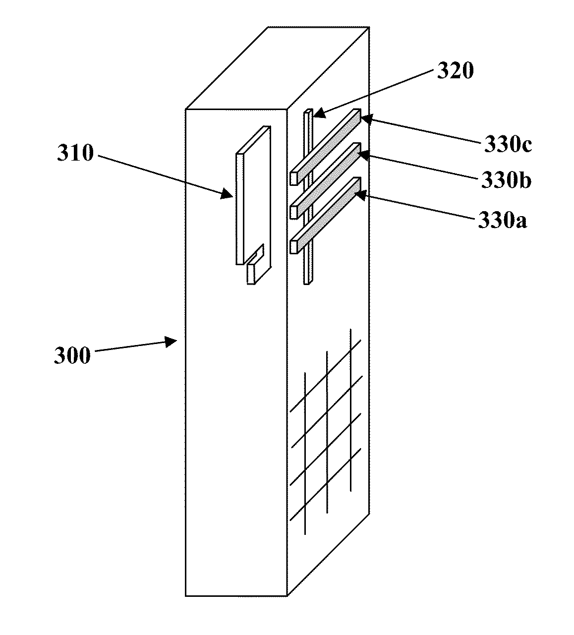
[0099]FIG. 3 illustrates a communication device 300 configured for mitigating undesired portions of electromagnetic radiation associated with an antenna 310 internal thereto in accordance with an embodiment of the present invention. The communication device 300 comprises a coupler 320, such as a strip of conductive material, which is substantially co-polarized with the antenna 310. The coupler is separated from the antenna 310 by a predetermined distance. The communication device further comprises a plurality of dissipaters 330a, 330b, 330c, each of which is substantially differently polarized from the antenna 310.

[0100]The communication device 300 may be a cellular telephone, wireless adapter, machine-type wireless communication device, or other wireless device, as would be readily understood by a worker skilled in the art.

[0101]The coupler 320 and dissipaters 330a, 330b, 330c may be integrally formed with the communication device 300, or attached thereto by soldering, adhesive, fa...

example 3

[0102]FIG. 4 illustrates an apparatus 400 for mitigating undesired portions of electromagnetic radiation associated with an antenna in accordance with an embodiment of the present invention. The apparatus 400 is mounted on a housing 410 for example of a communication device. The housing 410 contains an antenna (not shown) which is associated with a hotspot 415. The apparatus 400 is located within the hotspot 415, and configured to mitigate the hotspot.

[0103]As illustrated in FIG. 4, the apparatus 400 comprises two couplers 420, 425, substantially co-polarized with the antenna and EM inductively coupled thereto. The apparatus further comprises dissipaters 440a, 440b, 440c, 440d, 440e EM inductively coupled to coupler 420, and dissipaters 445a, 445b, 445c, 445d, 445e EM inductively coupled to coupler 425. The dissipaters are substantially cross-polarized with the antenna. The apparatus further comprises an insulating or dielectric layer 430 or air gap between the couplers and dissipat...


PUM


Abstract

The present invention relates to an apparatus for mitigating undesired portions of electromagnetic radiation (EMR) associated with an antenna. The apparatus comprises a coupling element EM inductively coupled with the antenna, the coupling element being substantially co-polarized with the antenna. The apparatus further comprises one or more dissipating elements EM inductively coupled with the coupling element, each of the one or more dissipating elements being substantially differently polarized than the antenna, for example cross-polarized to the antenna. The coupling element may be a conductive element configured for predetermined EM inductive coupling with at least the antenna and the one or more dissipating elements. Each of the one or more dissipating elements may be a conductive element configured for predetermined EM inductive coupling with the coupling element. A method of manufacture is also provided.

Description

FIELD OF THE INVENTION[0001]The present invention pertains in general to systems of passive elements that absorb and reradiate electromagnetic radiation, and in particular to a method and apparatus for mitigating undesired portions of electromagnetic radiation (EMR) associated with an antenna.BACKGROUND[0002]In many wireless communication devices such as cellular telephones, wireless-enabled laptops, wireless-enabled personal digital assistant (PDA) devices, and the like, radio transmitters are often situated in close proximity to a human user. There is currently concern that exposure to electromagnetic radiation emitted by such transmitters may pose a health risk to the user or other persons sufficiently close to the transmitter. Undesired electromagnetic radiation may also interfere with operation of nearby electronics or communication devices.[0003]To reduce health risks, regulatory bodies such as the FCC have mandated limits for safe exposure to radio frequency (RF) energy corre...

Claims


Application Information

Patent Timeline
Patent Type & Authority Applications(United States)
IPC IPC(8): H01Q1/52H01Q1/24
CPCH01Q1/245H01Q19/28
Inventor YEN, CHIH-CHUAN
Owner NETGEAR INC
Why Eureka
Try Eureka