Hand-held power jigsaw

a power jigsaw and hand-held technology, applied in the field of hand-held jigsaws, can solve the problems of blades going astray, requiring a large amount of practice, and requiring additional work, and achieve the effect of simple and inexpensive fashion

Inactive Publication Date: 2012-01-05
KAISER HANS +7
View PDF21 Cites 17 Cited by
  • Summary
  • Abstract
  • Description
  • Claims
  • Application Information

AI Technical Summary

Benefits of technology

[0007]The system is used to assist an operator and therefore to facilitate the sawing procedure. Taking advantage of the existing degree of freedom of the saw blade in the form of the already implemented rotation axis, the hand-held jigsaw is equipped with a special sensor system for detecting a previously drawn line or layout line and a corresponding actuator system for automatically adjusting the saw blade angle from an angle range of a pivot angle. The rotation axis here is defined by a normal that extends through a center point of a plane defined by a thickness and a width of the saw blade. Alternatively, the rotation axis of the saw blade can also be situated other than at its center point. In this case, the pivot angle represents the angle by which the saw blade can be maximally adjusted around its longitudinal axis in relation to a longitudinal axis of the glide element and / or another guidance component deemed suitable by a person skilled in the art, e.g. a chassis. This pivot angle is preferably an angle of between 0° and 90°. By contrast, the saw blade angle of the saw blade is the angle that is actually set between the lateral span of the saw blade and the longitudinal axis of the glide element or a guidance component. By means of a saw blade motion that is overlaid with a hand-guided movement of the operator, it is possible to more precisely track a previously drawn contour. Straight cuts can also be implemented without additional guides.
[0015]According to the invention, a display element is produced, which is provided to display a recommended advancing direction. A “display element” is understood here to mean an element that optically, acoustically, and / or tactilely informs the operator of the path detected by a sensor or of a course of the layout line. The display element here can be composed of LEDs and / or a display and / or another data unit deemed suitable by a person skilled in the art. This makes it advantageously possible for an operator to receive information relating to a desired movement direction, regardless of whether the operator is able to see the saw blade. This makes it possible for an operator to stay within an optimal working region that represents an angular range of the possible saw blade angle.

Problems solved by technology

Without additional guidance-assisting elements, sawing precisely along a predetermined contour with a jigsaw requires a large amount of practice.
This task is additionally complicated by the exertion of transverse forces that cause the saw blade to go astray.
Providing laterally supporting assistance systems or various navigation aids (e.g. lasers) reduces these problems, but does not eliminated them.

Method used


Image

  • Hand-held power jigsaw
  • Hand-held power jigsaw
  • Hand-held power jigsaw

Examples


Embodiment Construction

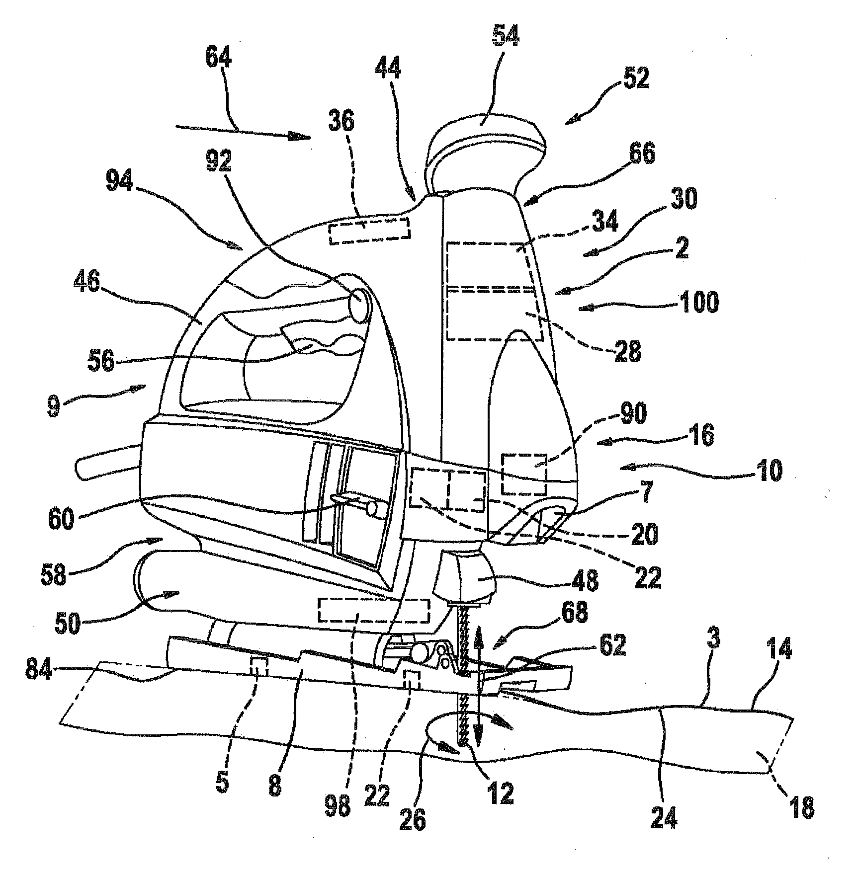
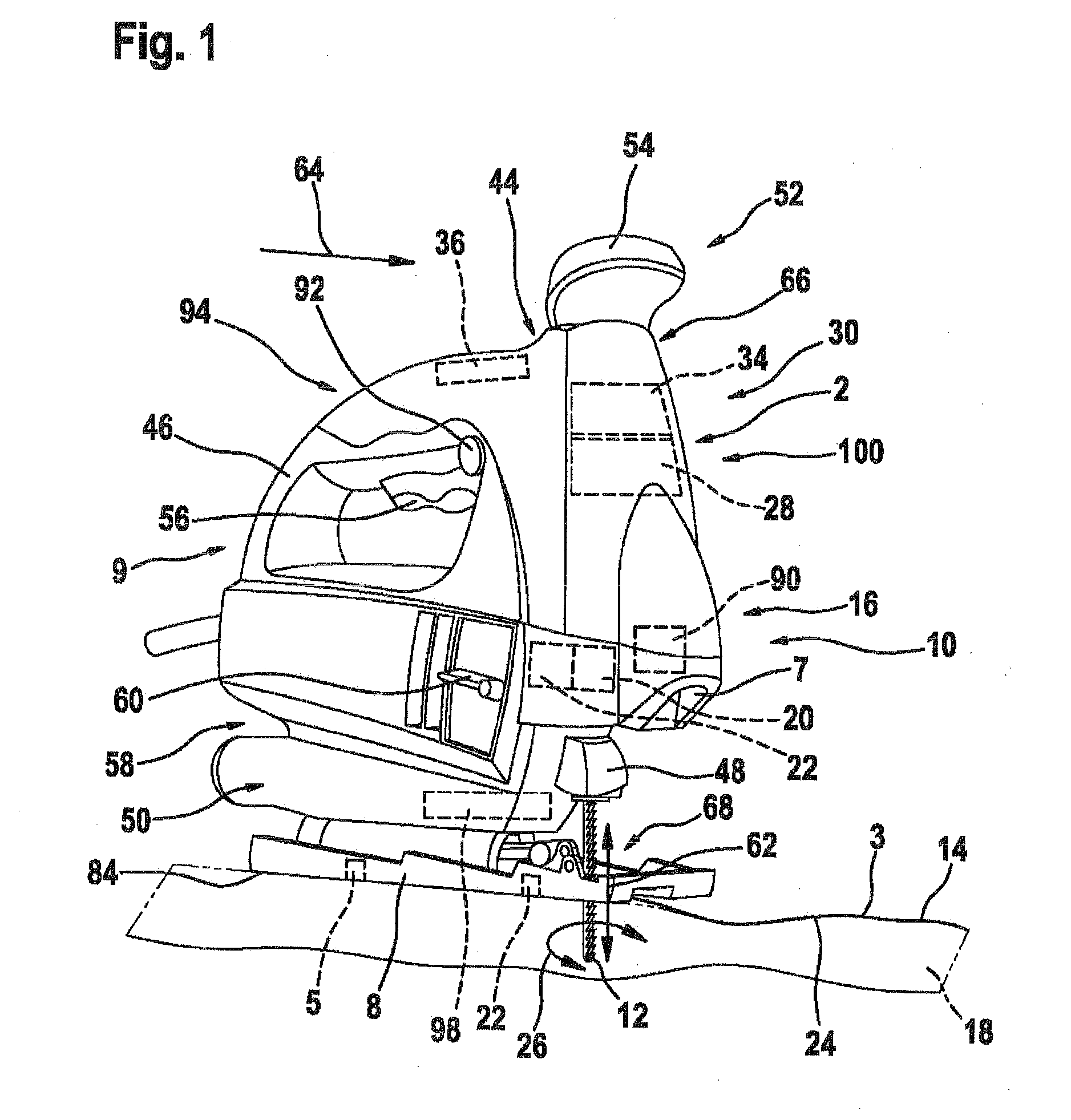
[0022]FIG. 1 is a perspective side view of a hand-held jigsaw 9 according to the invention, embodied in the form of a scrolling jigsaw. The hand-held jigsaw 9 includes a machine housing 44, a main handle 46 integrated into the machine housing 44, and a tool socket 48 containing a tool in the form of a rotatably supported saw blade 12. A glide element or glide shoe 8 in the form of a base plate is situated on a side 50 oriented toward the work piece 18 to be machined. This glide shoe 8 permits the hand-held jigsaw 9 to advantageously glide on the work piece 18. On the side 52 oriented away from the saw blade 12, in a region that can be associated with the main handle 46, a guide knob is provided, which is used for an at least manual guidance of the hand-held jigsaw 9. The machine housing 44 also contains a motor that is not shown in detail. On the main handle 46, an actuation switch 56 is provided, which can be used to switch the hand-held jigsaw 9 on and off. In a side region 58 of ...


PUM

PropertyMeasurementUnit
angleaaaaaaaaaa
angleaaaaaaaaaa
blade angleaaaaaaaaaa

Abstract

A hand-held jigsaw includes a saw blade and control element for automating a tracking the saw blade, the hand-held jigsaw, or both along layout lines. A sensor, preferably a camera unit, detects a layout line provided on a work piece.

Description

CROSS-REFERENCE TO RELATED APPLICATIONS[0001]The present invention is a divisional application of co-pending U.S. application Ser. No. 12 / 281,442, filed Sep. 2, 2008. The invention described and claimed hereinbelow is also described in German Patent Application DE 10 2006 052 608.5 filed on Nov. 9, 2006. These German Patent Applications, whose subject matter is incorporated here by reference, provides the basis for a claim of priority of invention under 35 U.S.C. 119(a)-(d).BACKGROUND OF THE INVENTION[0002]The present invention is based on a hand-held jigsaw.[0003]For example, the publications US 2005 / 0060896 A1 and US 2005 / 0257985 A1 have disclosed jigsaws that are referred to as “scrolling jigsaws” and in which the saw blade is situated so that in addition to executing the stroke motion, it can be rotated manually independently of the sawing motion. This additional function facilitates the sawing of sinuous cuts.[0004]Without additional guidance-assisting elements, sawing precisel...

Claims


Application Information

Patent Timeline
Patent Type & Authority Applications(United States)
IPC IPC(8): B23D51/02B23D49/16
CPCB23D49/167B23D59/002B23D51/02Y10T83/531Y10T83/828
Inventor KAISER, HANSMARX, KLAUSDELFINI, STEFANONIEHSEN, WOLFGANGKOEDER, THILOFLINSPACH, GUNTERFRANGEN, JOACHIMPLATZER, JOACHIM
Owner KAISER HANS
Why Eureka
Try Eureka