Optical recovery of radiographic geometry

a radiographic geometry and optical recovery technology, applied in the field of radiographic imaging, can solve the problems of preventing the use of these systems, obtaining or maintaining the geometry, and inaccuracy of the generated three-dimensional radiographic information, and achieve the effect of facilitating procedures

Inactive Publication Date: 2005-12-20
CANON KK
View PDF13 Cites 87 Cited by
  • Summary
  • Abstract
  • Description
  • Claims
  • Application Information

AI Technical Summary

Benefits of technology

[0011]By virtue of the foregoing, the present invention generates three-dimensional radiographic information on a subject even in situations where the geometry of the system is unstable or unknown. By calculating the radiographic geometry using visible light images, the invention has the advantage of not requiring error-prone measurement and calibration of the entire system when obtaining the radiographic images. Additionally, since the geometry is recovered by applying stereoscopic analysis to visible light images, the invention does not require the use of markers or radiopaque fiducials which can obscure data and require additional set-up and installment procedures and measurements. Finally, by obtaining visible light images in correspondence with radiographic images, the visible surface structure of a subject can be reconstructed and registered with the corresponding internal structure of the subject shown in the radiographic images, so as to facilitate procedures such as reconstructive plastic surgery.

Problems solved by technology

The requirement that these measurements be precise throughout the process of obtaining the multiple radiographic images often prevents the use of these systems in situations where it is difficult to obtain or maintain the geometry.
Additionally, slight variations in the obtained measurements or the calibration process can lead to inaccuracies in the generated three-dimensional radiographic information.
However, these systems have the disadvantage of requiring multiple visible light cameras configured in multiple directions relative to the subject as well as requiring the use of markers attached to the subject.
These types of systems also have disadvantages in that the use of radiopaque fiducials is required and the radiopaque fiducials can obscure portions of the radiographic image.

Method used


Image

  • Optical recovery of radiographic geometry
  • Optical recovery of radiographic geometry
  • Optical recovery of radiographic geometry

Examples


first embodiment

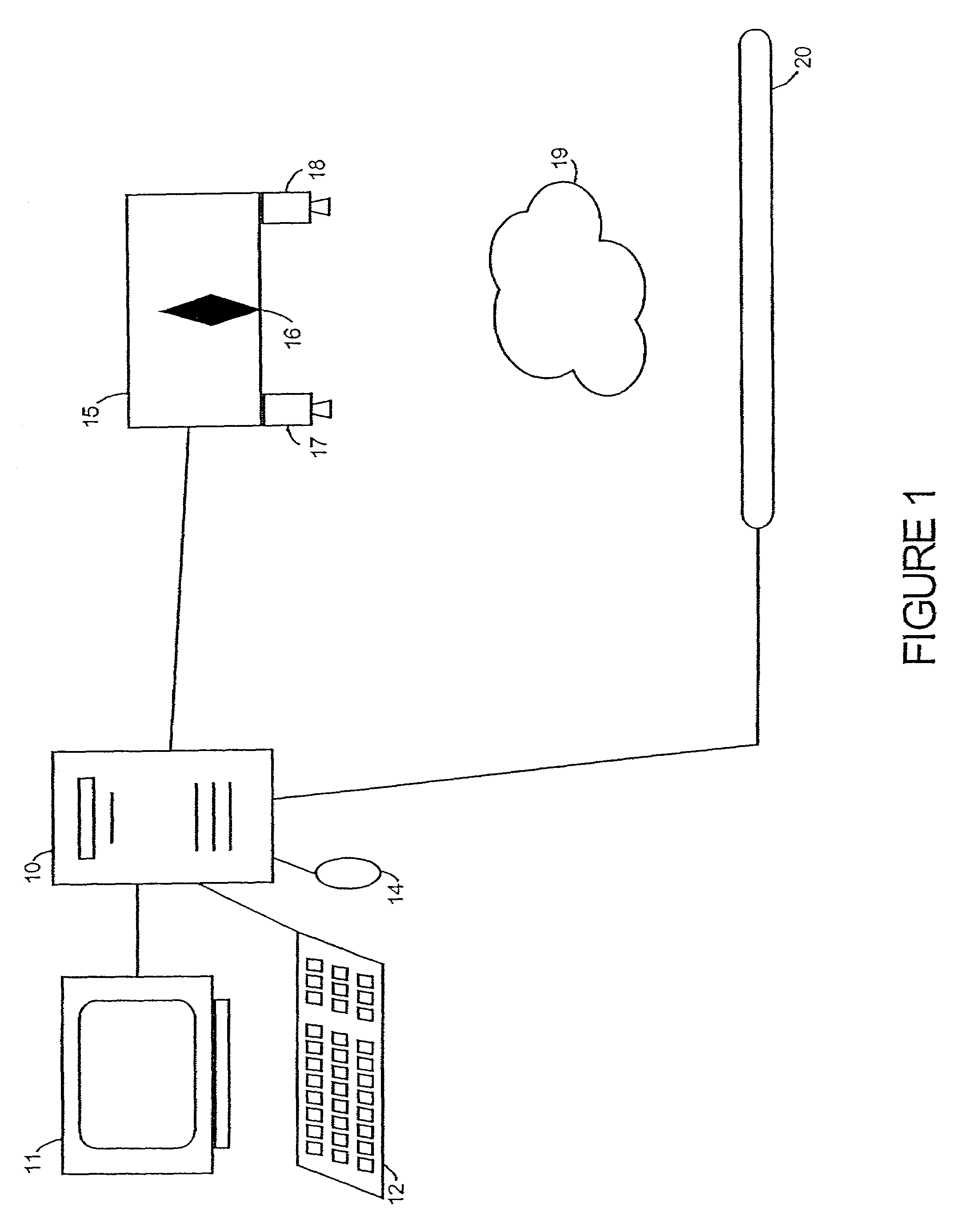
[0040]FIG. 5 depicts representative positioning of the radiographic system according to the invention. In order to generate three-dimensional radiographic information from two-dimensional radiographic images, the two-dimensional radiographic images are acquired from different positions relative to subject 19. In this embodiment, imaging head 15, together with x-ray source 16 and cameras 17 and 18, are moved along a direction indicated by arrow A while irradiating subject 19 from different positions along arrow A. For example, from a first position at 43a to a second position (shown in phantom lines) at 43b. Arrow A is a direction parallel to sensor 20, thereby keeping the distance between x-ray source 16, and therefore also cameras 17 and 18, and sensor 20 constant for each of the different positions. Additionally, in this embodiment subject 19 is in a fixed position relative to sensor 20 and therefore the only element changing positions during the acquisition of radiographic images...

second embodiment

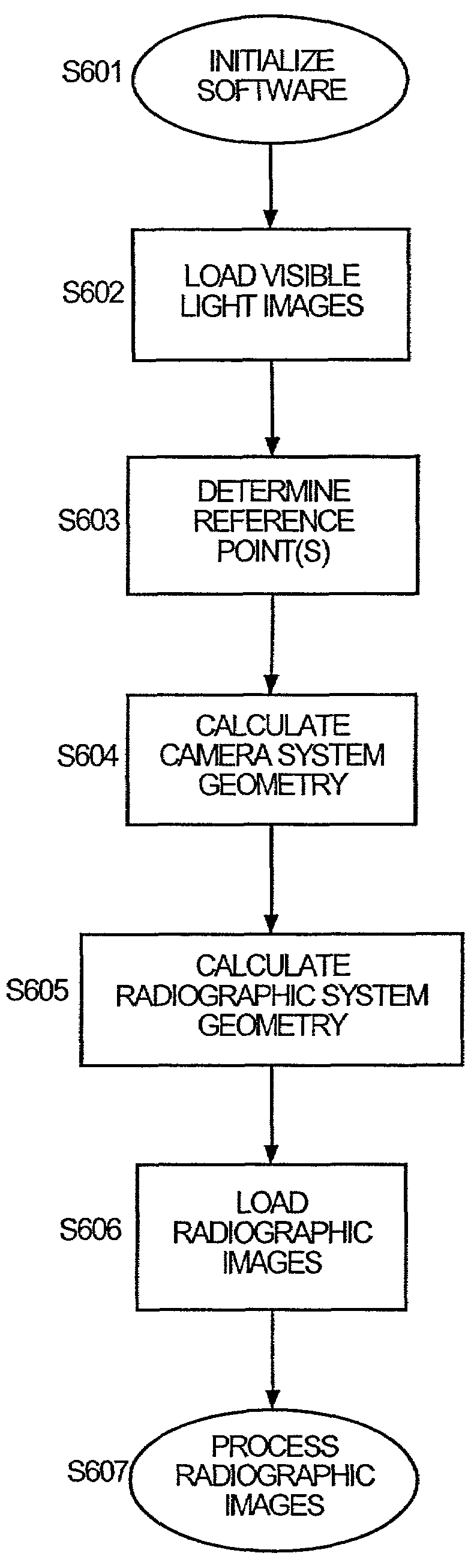
[0074]Radiographic and visible light images are acquired of subject 19 according to the process described above with reference to the flowchart depicted in FIG. 4. In addition to positioning imaging head 15, together with x-ray source 16 and cameras 17 and 18, in step S402, sensor 20 is also positioned in step S402 in the manner described above with reference to FIG. 9. Once the desired images have been acquired, the radiographic images and visible light images are processed according to the procedure described above with reference to FIG. 6. Variations in the procedure are described below.

[0075]FIG. 10 is a representative example of the system geometry in the second embodiment of the invention with respect to cameras 17 and 18 and subject 19. For purposes of explanation, some of the elements of the radiographic system have been excluded from FIG. 10. In the second embodiment, imaging head 15 is moved through an arc indicated by arrow AA. Cameras 17 and 18, which move together with...

third embodiment

[0085]Unlike the first two embodiments, the distance between imaging head 15 and sensor 20 is not constant during the process of obtaining the radiographic images. Accordingly, the relative positions of imaging head 15 and sensor 20 must be obtained for each position of imaging head 15. As discussed above, the relative position of sensor 20 can be derived using the visible light images and identifying a reference point on sensor 20. Using the procedures discussed above with respect to determining the relative positions of subject 19 and x-ray source 16, the relative position of sensor 20 is obtained. However, in the process discussed above, the process of determining the relative position of sensor 20 only used a single reference point on sensor 20. In the third embodiment, since imaging head 15 partially rotates around the position of sensor 20, as depicted in FIG. 11, the plane in which sensor 20 lies with respect to x-ray source 16 is recovered in order to determine the relative ...


PUM


Abstract

Processing of up to a plurality of radiographic images of a subject, includes the capture of at least two visible light images of the subject, two or more of the visible light images in correspondence to at least one radiographic image. The visible light images are captured by one or more visible light cameras, each visible light camera in a known geometric relation to the radiographic source. Radiographic geometry of each radiographic image is calculated relative to the radiographic source and the subject through stereoscopic analysis of the visible light images and through reference to the known geometric relation between the one or more visible light cameras and the radiographic source. Three-dimensional radiographic information on the subject is generated and manipulated by processing the up to a plurality of radiographic images based on the recovered radiographic geometry.

Description

BACKGROUND OF THE INVENTION[0001]1. Field of the Invention[0002]The present invention concerns radiographic imaging and in particular concerns the use of an optical camera system to recover the radiographic geometry of a radiographic system, and the use of the recovered radiographic geometry to generate and manipulate three-dimensional radiographic information from radiographic images.[0003]2. Description of the Related Art[0004]Radiographic imaging provides a valuable diagnostic tool with both medical and industrial applications. From standard two-dimensional radiographic images, three-dimensional radiographic information can be generated. For example, stereoscopic x-ray imaging techniques process a pair of radiographic images taken from different positions relative to a subject, and generate images of the subject that appear to be three-dimensional when viewed with the proper equipment. As another example, tomosynthesis synthesizes images of internal slices of a subject at specifi...

Claims


Application Information

Patent Timeline
Patent Type & Authority Patents(United States)
IPC IPC(8): A61B6/02G06T7/00
CPCA61B6/025G06T7/0018G06T7/0022A61B6/022G06T7/80G06T7/97
Inventor BERESTOV, ALEXANDER LEONIDOVICH
Owner CANON KK
Why Eureka
Try Eureka