Introducing a false bottom into a lauter tun

a technology applied in the field of false bottoms and lauter tunics, can solve the problem of saving a considerable amount of spa

Inactive Publication Date: 2012-01-05
KRONES AG
View PDF8 Cites 0 Cited by
  • Summary
  • Abstract
  • Description
  • Claims
  • Application Information

AI Technical Summary

Benefits of technology

[0005]Starting from this situation, one aspect underlying the present disclosure is to provide a method and a l...

Problems solved by technology

Thus, one can save a considerable amount of space as the lauter tun ...

Method used


Image

  • Introducing a false bottom into a lauter tun
  • Introducing a false bottom into a lauter tun
  • Introducing a false bottom into a lauter tun

Examples


Embodiment Construction

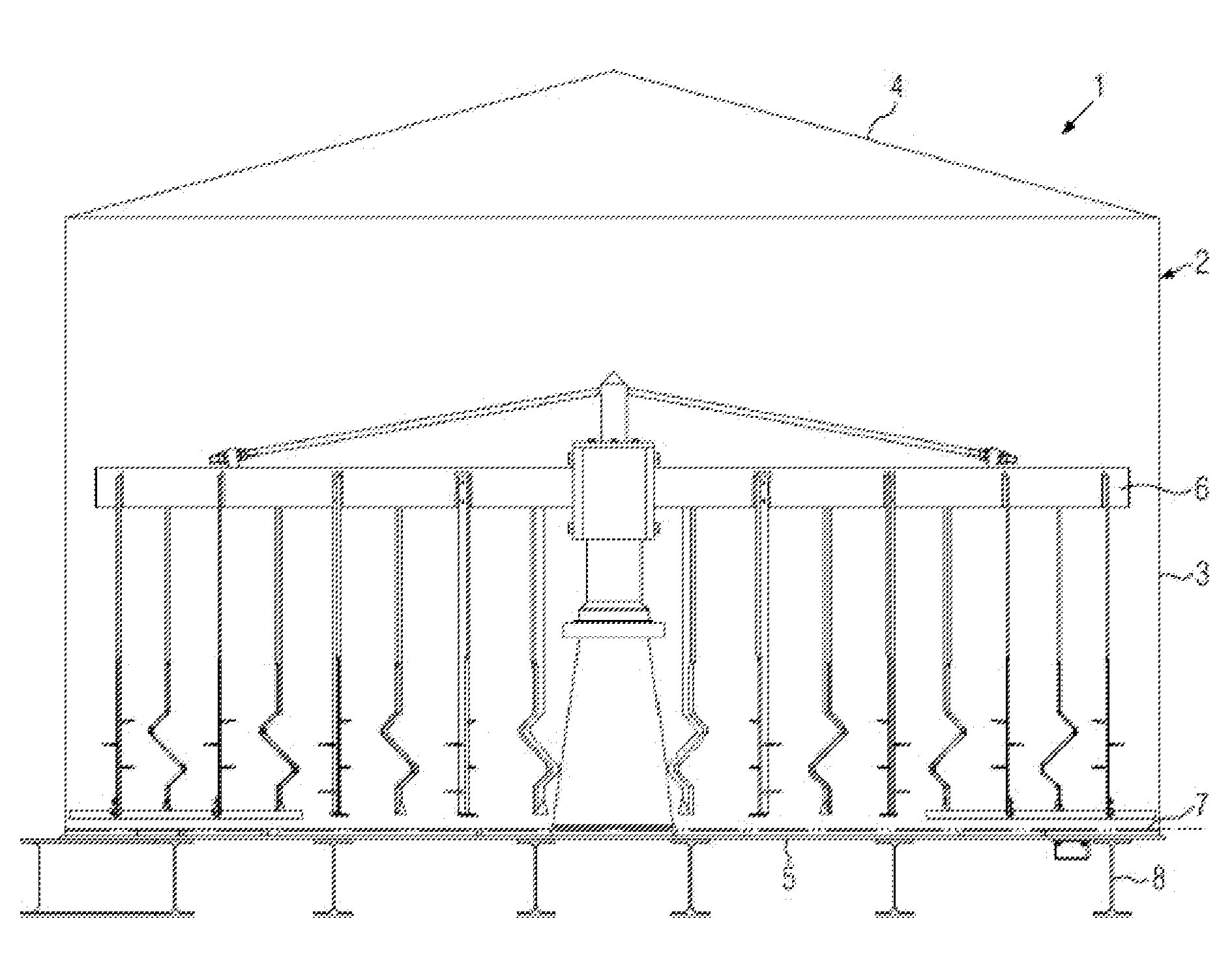
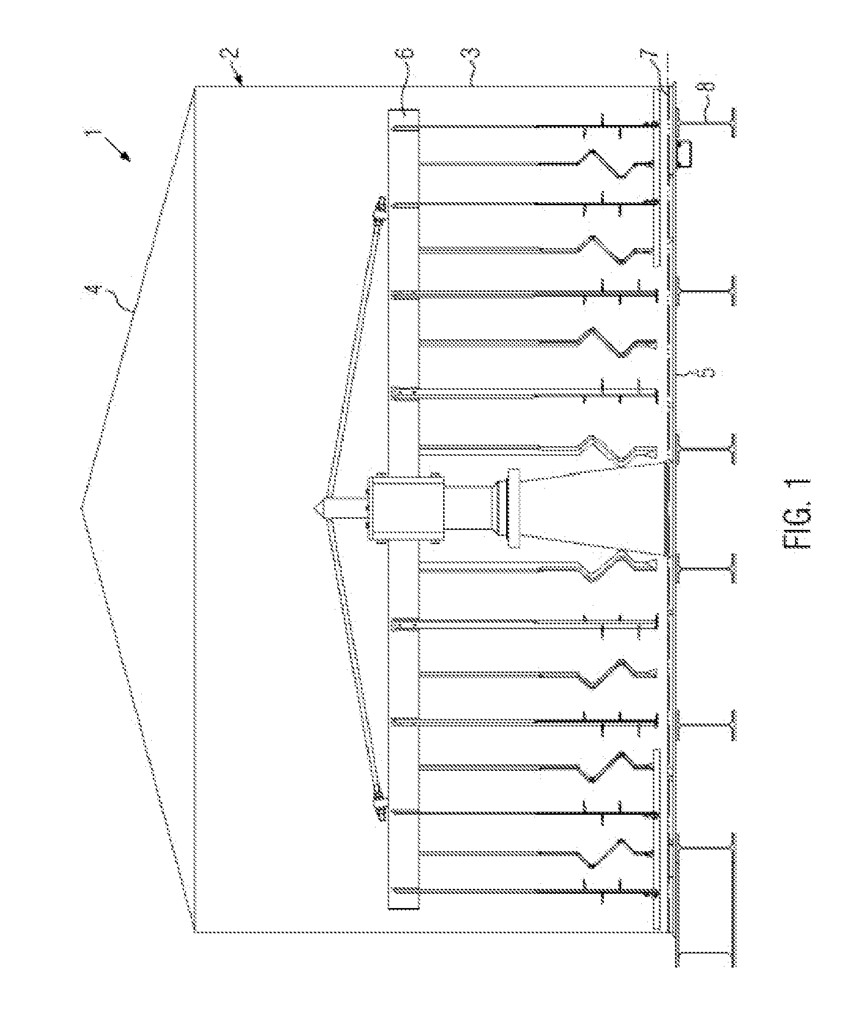
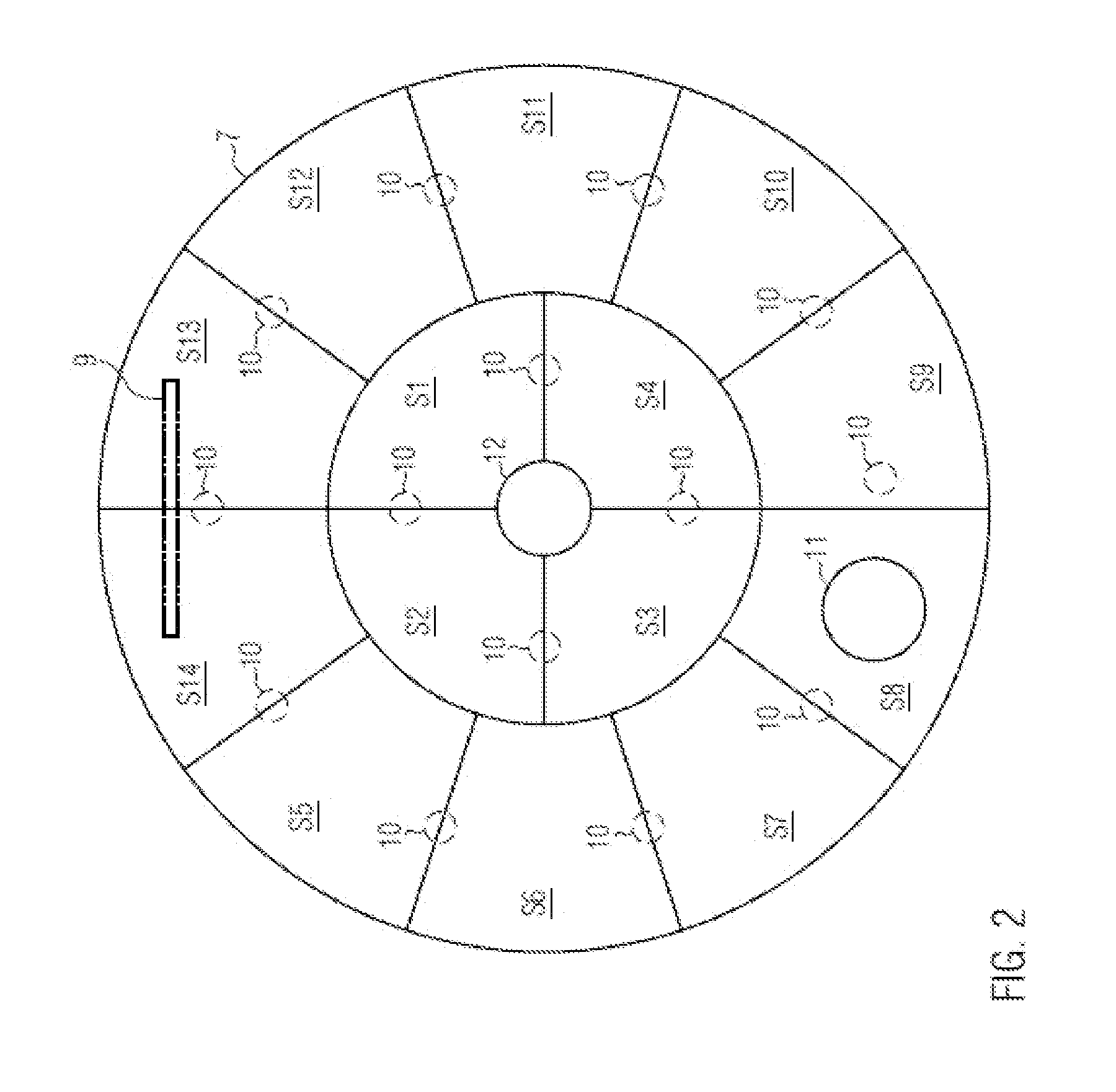
[0023]FIG. 1 shows a longitudinal section through a possible embodiment of a lauter tun 1 according to the present disclosure. In a well-known manner, a lauter tun comprises a lauter tun container 2 which here comprises e.g. a cylindrical wall 3, a hood 4 as well as a lauter tun bottom 5. The lauter tun bottom 5 is here arranged on bars, e.g. double T-bars 8, and can be fixed, for example, on a supporting frame by means of these bars. A second insertable false bottom 7 divided into several elements or segments S1 to S14 (see FIG. 2) is provided over the lauter tun bottom 5. The distance between the false bottom 7 and the tun bottom 5 is between 10 mm and 60 mm, e.g. approx. 20 mm. As can be taken from FIG. 2, the false bottom is divided into several false bottom elements which rest on corresponding support elements (not represented). In particular, the support elements are firmly connected to the bottom side of the false bottom elements. In FIG. 2, 14 false bottom elements S1 to S14...


PUM


Abstract

A method of introducing a false bottom comprising several false bottom elements into a lauter tun container, as well as a corresponding lauter tun, where, to introduce the false bottom or the false bottom elements, a false bottom introduction opening is provided in the lauter tun bottom through which the false bottom elements are introduced into the lauter tun container from the bottom.

Description

CROSS-REFERENCE TO RELATED APPLICATION[0001]The present application claims the benefit of priority of German Application No. 102010030888.9, filed Jul. 2, 2010. The entire text of the priority application is incorporated herein by reference in its entirety.FIELD OF THE DISCLOSURE[0002]The disclosure relates to a method of introducing a false bottom and to a lauter tun such as used in beer production.BACKGROUND[0003]During lautering, a solid-liquid separation of the mash takes place. The liquid, also referred to as wort, is used for further wort or beer production. The solid components, referred to as spent grains, are a residual product which is used, for example, as fodder or for energy generation. The lauter tun is one of the oldest and widest spread lauter apparatuses. The lauter tun comprises a container over the bottom of which a slotted false bottom is provided. The mash is guided into the container, where the spent grains remain lying on the false bottom and the wort can drai...

Claims


Application Information

Patent Timeline
IPC IPC(8): C12G1/02B23P17/04
CPCC12C7/17Y10T29/49826C12C13/00
Inventor DEUTER, PETER
Owner KRONES AG
Why Eureka
Try Eureka