Double Wall Pipe

a technology of wail pipe and spherical pipe, which is applied in the direction of pipe elements, tubular elements, light and heating equipment, etc., can solve the problems of not defined touching surfaces between components, mechanical damage, and limited life of distance holders, and achieve the effect of preventing stress and achieving the same thermal expansion coefficien

Inactive Publication Date: 2008-12-25
GALL & SEITZ SYSTEMS GMBH
View PDF18 Cites 5 Cited by
  • Summary
  • Abstract
  • Description
  • Claims
  • Application Information

AI Technical Summary

Benefits of technology

[0017]According to an embodiment, of the invention, the inner pipe has a hardness degree greater than the protection pipe. Thus the very sensitive pressure pipe will hardly be effected daring the bending process. More exactly the material of the protection tube must be chosen, in that way, that even using extreme bonding angles and / or radii the pressure pipe is not affected by mechanical damages like any grooves or surface failures.
[0018]In order to prevent stress in the unified double wall pipe by heat variations, the material of the inner pine has substantially the same thermal expansion coefficient than the material of the protection pipe.

Problems solved by technology

Such distance holders have only limited life lime caused by different vibrations of these two components.
For this reason, after not specified time the protection hose gets in touch whit the pressure pipe and starts to cause mechanical damages.
The solution of using normal steel pipes as a protection tube causes the same problems of not defined touching surfaces between the components because of bending the pipe during the manufacturing process.
Contact corrosion can damage both pipes.
The vibrations from the engine cause different oscillations of the not uniform parts of the double wall fuel pipe.
Thus undefined different vibrations, undefined touching surfaces and other irregularities can damage both pipes.

Method used


Image

  • Double Wall Pipe
  • Double Wall Pipe

Examples


Embodiment Construction

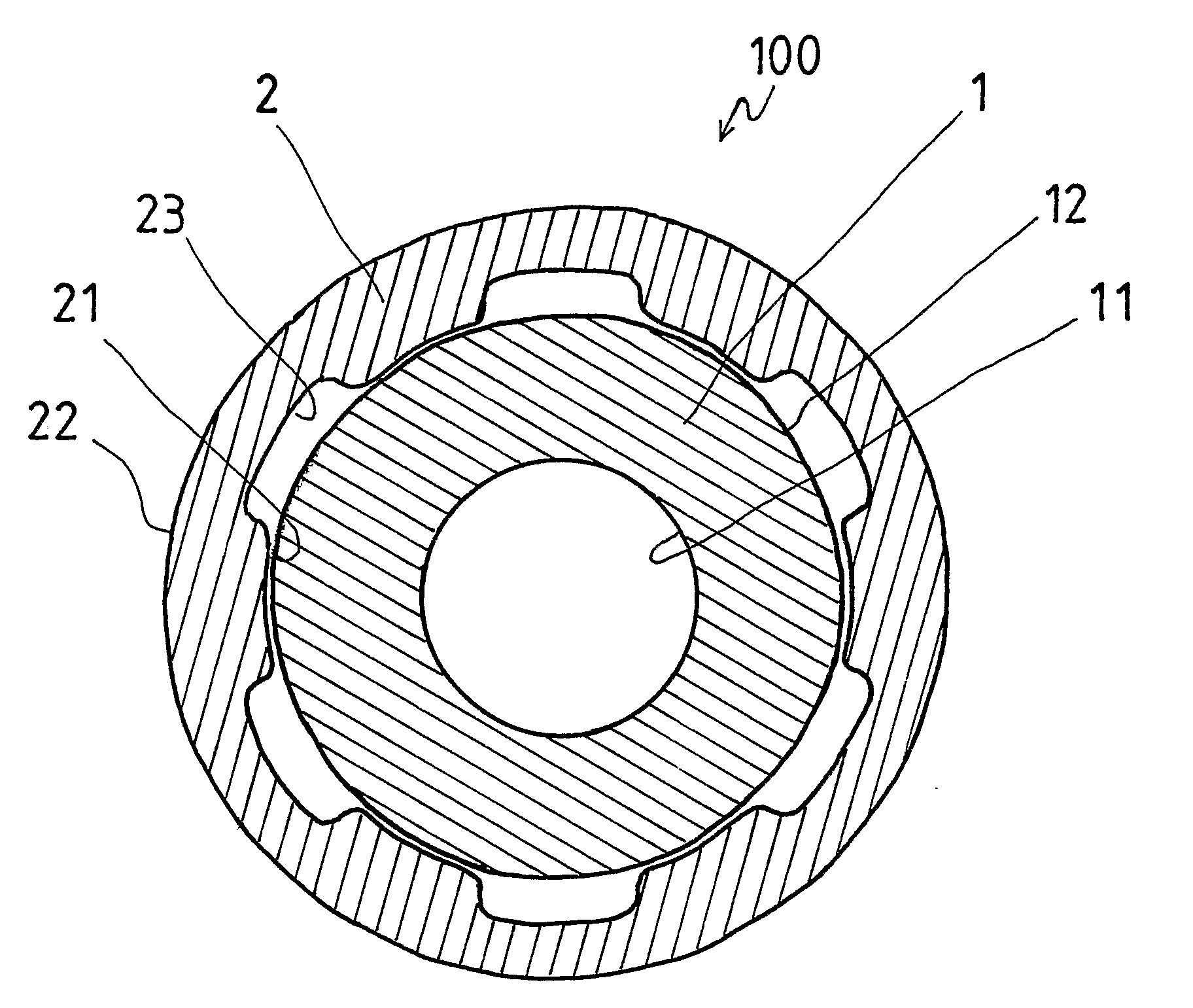
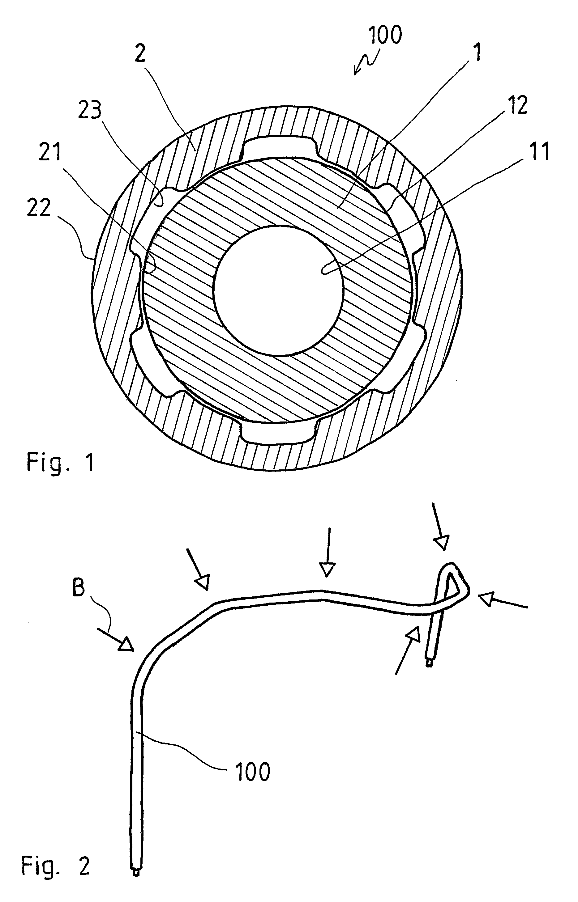
[0023]FIG. 1 shows a cross sectional view of a double wall pipe 100 consisting of en tuner high pressure pipe 1 and an outer protection pipe 2

[0024]The inner high pressure pipe 1 is a seam less precision steel tube of the material St 52.4. The finishing of the steel tube is preferred NBK. The steel tube contains in small tractions the elements C, Si, Mn, P, S and / or Al.

[0025]As an example, large diesel engines especially used as main or auxiliary engine of ships and particularly for two stroke diesel engines the high pressure pipe 1 can have the following size: outer diameter OD1=20 mm, inner diameter ID1=9 mm with wail thickness of 5.5 mm. High pressure fuel injection pipes withstand test pressures up to 1.350 bar and bear up to 120° C.

[0026]For these requirements a high, precision steel tube with low roughness and only few defects on the inner surface 11 is necessary. Preferably, the inner surface 11 of the high pressure pipe 1 has a tolerance of + / −0.10 mm. Furthermore the outer ...


PUM


Abstract

The present invention relates to a double wall pipe with an inner high pressure pipe (1) having an inner flow space for harmful and/or flammable liquids, particularly fuel to be infected or hydraulic oil, and with an outer protection pipe (2) coaxially arranged around the inner pipe, having an enter flow space between inner pipe and outer pipe, for possibly leaking or spilling liquid from the inner pipe, wherein the protection pipe (2) has several substantially longitudinal arranged grooves (23) throughout its inner surface (21); the inner high pressure pipe (1) is fitted tightly into the protection pipe (2); and after bending the double wall pipe (100), the double wall pipe (100) is unified by surface pressure due to deformation of bending process.

Description

CROSS REFERENCE TO RELATED APPLICATION[0001]This application is a national stage of PCT / EP2004 / 010859 filed Sep. 28, 2004.BACKGROUND OF THE INVENTION[0002]1. Field of the Invention[0003]The present invention relates to a double wail pipe with an inner high pressure pipe having as inner flow space for harmful and / or flammable liquids, particularly fuel to be injected or hydraulic oil, and with an outer protection pipe coaxially arranged around the inner pipe, having an outer flow space between inner pipe and outer pips, for possibly leaking or spilling liquid from the inner pipe.[0004]2. Description of Related Art[0005]Industrial steel pipes, widen carry harmful and / or flammable liquids such as fuel, hydraulic oil, acid or others need to have an outer protection as a means of spill prevention. This type of spill prevention is compulsory for main and auxiliary engines on ships required by SOLAS, international convention for the safety of life at sea, regulations. Today standard is to ...

Claims


Application Information

Patent Timeline
Patent Type & Authority Applications(United States)
IPC IPC(8): F16L9/14
CPCF16L9/18F28F1/003G01M3/02F16L9/00
Inventor BUSCHHOFF, JORG
Owner GALL & SEITZ SYSTEMS GMBH
Why Eureka
Try Eureka