Cutting table for cutting a fiber preform obtained by three-dimensional weaving, and a cutting method using such a table

a cutting table and fiber preform technology, applied in the direction of severing textiles, metal working apparatus, textiles and paper, etc., can solve the problems of difficult manual control, inability to envisage waterjet cutting, and inability to meet the needs of textile workers, so as to facilitate the passage of a cutting tool, facilitate the cutting work of the operator, and optimize the retention of the preform

Active Publication Date: 2016-12-29
SN DETUDE & DE CONSTR DE MOTEURS DAVIATION S N E C M A
View PDF6 Cites 0 Cited by
  • Summary
  • Abstract
  • Description
  • Claims
  • Application Information

AI Technical Summary

Benefits of technology

[0010]Advantageously, the cutting template has at least two indexing fingers for positioning it on the preform. Likewise, the cutting template advantageously has a bevelled edge for facilitating the passage of a cutting tool. Finally, the cutting template advantageously has a compacting lip at its periphery for the purpose of optimizing retention of the preform while it is being cut out.
[0011]The tabletop is preferably rotary, circular, horizontal, and includes a top surface that is provided with the recess, thereby facilitating the cutting work of the operator.

Problems solved by technology

One of the problems encountered with making such preforms is that the profiles as cut out from the two non-interlinked portions of the preforms (constituting their final outlines) are not necessarily the same.
In such a situation, it is not possible to envisage using waterjet cutting, so it is necessary to cut out the profiles of the two portions of the preform manually, one after the other.
However, it is difficult to control manual cutting out of a fiber preform, which can lead to cutting inaccuracies, and to problems of reproducibility and of loss of fibers.

Method used


Image

  • Cutting table for cutting a fiber preform obtained by three-dimensional weaving, and a cutting method using such a table
  • Cutting table for cutting a fiber preform obtained by three-dimensional weaving, and a cutting method using such a table
  • Cutting table for cutting a fiber preform obtained by three-dimensional weaving, and a cutting method using such a table

Examples


Embodiment Construction

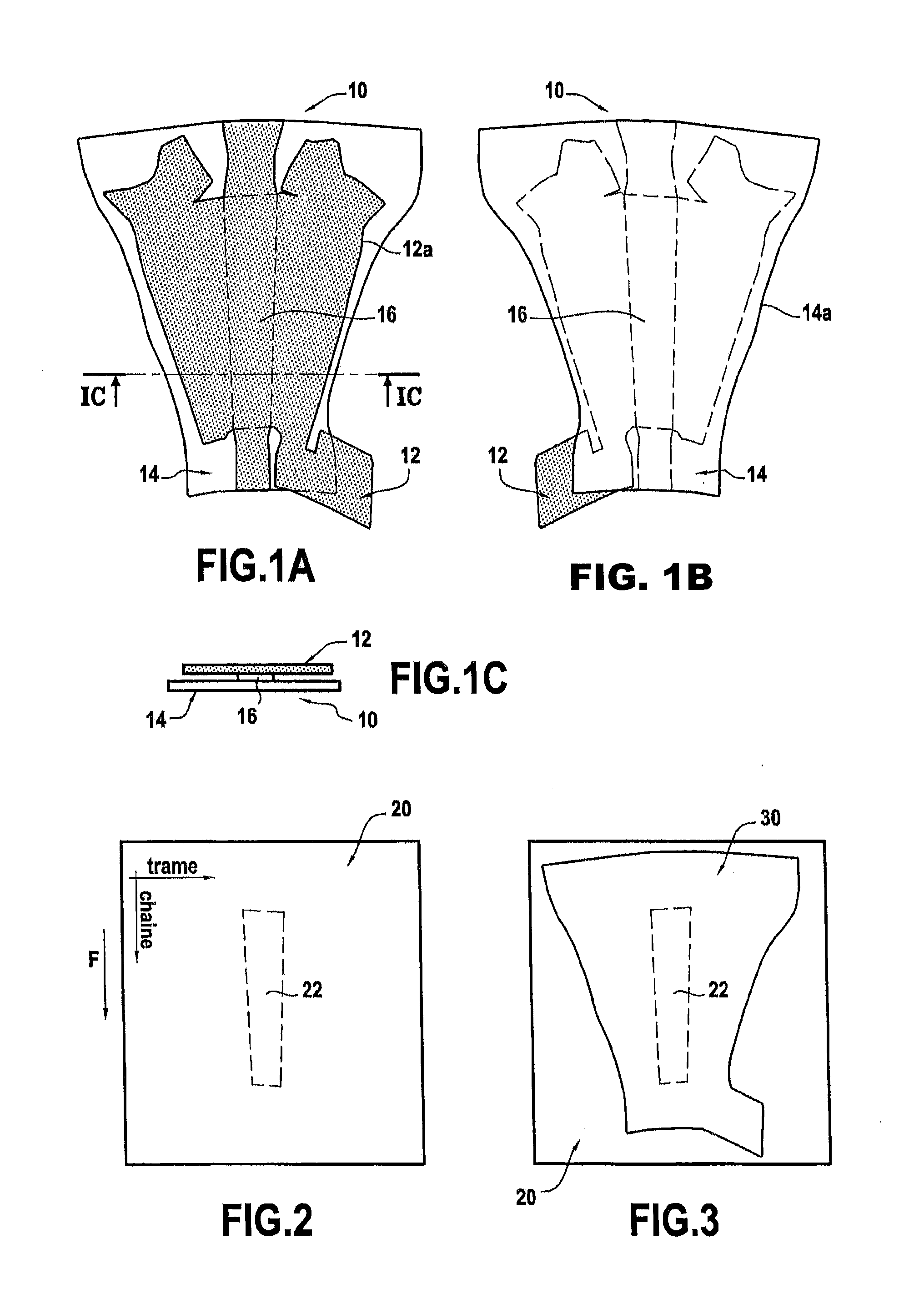
[0025]The invention relates to cutting out a fiber preform obtained by three-dimensional (3D) weaving and having two portions that are connected together by at least one zone of non-interlinking and that present outlines of different shapes. Such fiber preforms make it possible to make composite material parts of complex shape from a single flat-woven preform. A non-limiting example application is that of fiber preforms used for fabricating fan blade platforms for an aviation turbine engine, such as the preform shown in FIGS. 1A to 1C.

[0026]These figures are diagrams showing a fiber preform 10 that is obtained by 3D weaving and that, after shaping, injecting resin or densifying with a matrix, and possibly machining, serves to obtain a fan blade platform.

[0027]The term “3D weaving” should be understood as meaning that the warp yarns of the preform follow sinuous paths in order to interlink weft yarns belonging to different weft yarn layers, excepting zones of non-interlinking, it bei...


PUM

PropertyMeasurementUnit
compacting pressureaaaaaaaaaa
angleaaaaaaaaaa
widthaaaaaaaaaa

Abstract

A cutting table for cutting a fiber preform obtained by three-dimensional weaving and having two portions that are connected together by at least one zone of non-interlinking and that present outlines of different shapes, the cutting table including: a tabletop provided with a recess for receiving flat one of the portions of the preform to be cut; sacrificial plates for interposing between the portions of the preform for cutting and for being fastened to the tabletop; at least one cutting template designed to be pressed against the portion of the fiber preform that is not positioned in the recess; and a device for applying compacting pressure against the cutting template.

Description

BACKGROUND OF THE INVENTION[0001]The present invention relates to the general field of fiber preforms obtained by three-dimensional weaving and comprising two distinct portions that present outlines of different shapes and that are connected together by a zone of non-interlinking.[0002]Certain fiber preforms obtained by three-dimensional weaving include zones of non-interlinking that make it possible, using a single flat-woven preform, to make parts out of composite material that are complex in shape. For example, they might be fan blade platforms for an aviation turbine engine that can be obtained from n-shaped fiber preforms having a base and two legs forming stiffeners, the base constituting one portion and the two legs constituting another portion that is distinct from the base portion, the portions being connected together by a zone of non-interlinking.[0003]One of the problems encountered with making such preforms is that the profiles as cut out from the two non-interlinked po...

Claims


Application Information

Patent Timeline
Patent Type & Authority Applications(United States)
IPC IPC(8): B26D7/20D06H7/24B26F3/00
CPCB26D7/20B26F2210/12D06H7/24B26F3/008D06H7/00Y10T83/68
Inventor MATHON, RICHARD
Owner SN DETUDE & DE CONSTR DE MOTEURS DAVIATION S N E C M A
Why Eureka
Try Eureka