
Finish horizontal reinforcing rib-ring force

a technology of rib-ring force and finish, which is applied in the field of container, can solve the problems of spherulitic morphology, interfere with light transmission, and opaque material, and achieve the effect of improving structural integrity, resisting deflection and/or deformation, and increasing the hoop strength of finish 20

Active Publication Date: 2012-01-05
AMCOR RIGID PLASICS USA LLC
View PDF69 Cites 23 Cited by
  • Summary
  • Abstract
  • Description
  • Claims
  • Application Information

AI Technical Summary

Benefits of technology

The patent text describes a new way to make containers for holding hot food products. The containers have a special neck finish that is designed to be blow molded and has good structural integrity. This new design helps to maintain the seal integrity and recommended closure removal torque when the container comes in contact with the hot food product. The technical effect of this patent is to improve the quality of containers for high temperature food products.

Problems solved by technology

On amorphous material, thermal processing of PET material results in a spherulitic morphology that interferes with the transmission of light.
In other words, the resulting crystalline material is opaque, and thus, generally undesirable.
Unfortunately, with some applications particularly those relating to high temperature food products (i.e. applesauce, pasta sauces, salsa, etc.) where the product is packaged and / or dispensed at high temperatures, it is often desirable to package these products in containers having wide mouth finish openings to permit convenient access to the product using a spoon or other cooking implement.
This approach was less economical due to low injection cavitation and the need for secondary processing to crystallize the neck finish after the preform part was produced.
The combination of reduced rigidity, heat time duration, and the inward force from the closure, results in finish movement which then reduces the closure removal torque and possibly the seal integrity.
Therefore, although to date, preform design, mold temperature, and processing have produced blown neck finishes with an average crystallinity above 25%, it appears that the neck finish continues to experience disadvantageous movement resulting in low removal torque.

Method used


Image

  • Finish horizontal reinforcing rib-ring force
  • Finish horizontal reinforcing rib-ring force
  • Finish horizontal reinforcing rib-ring force

Examples


Embodiment Construction

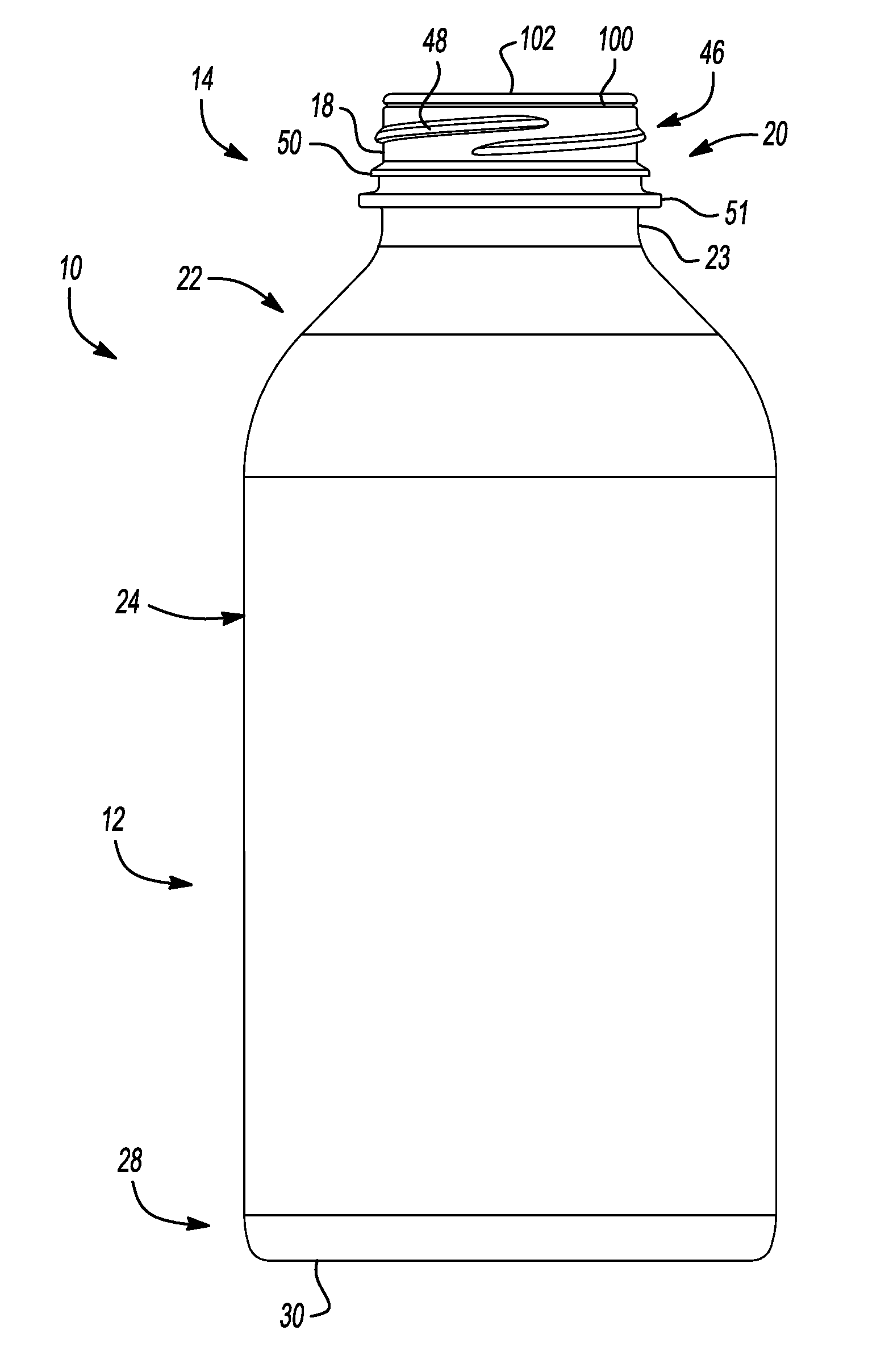
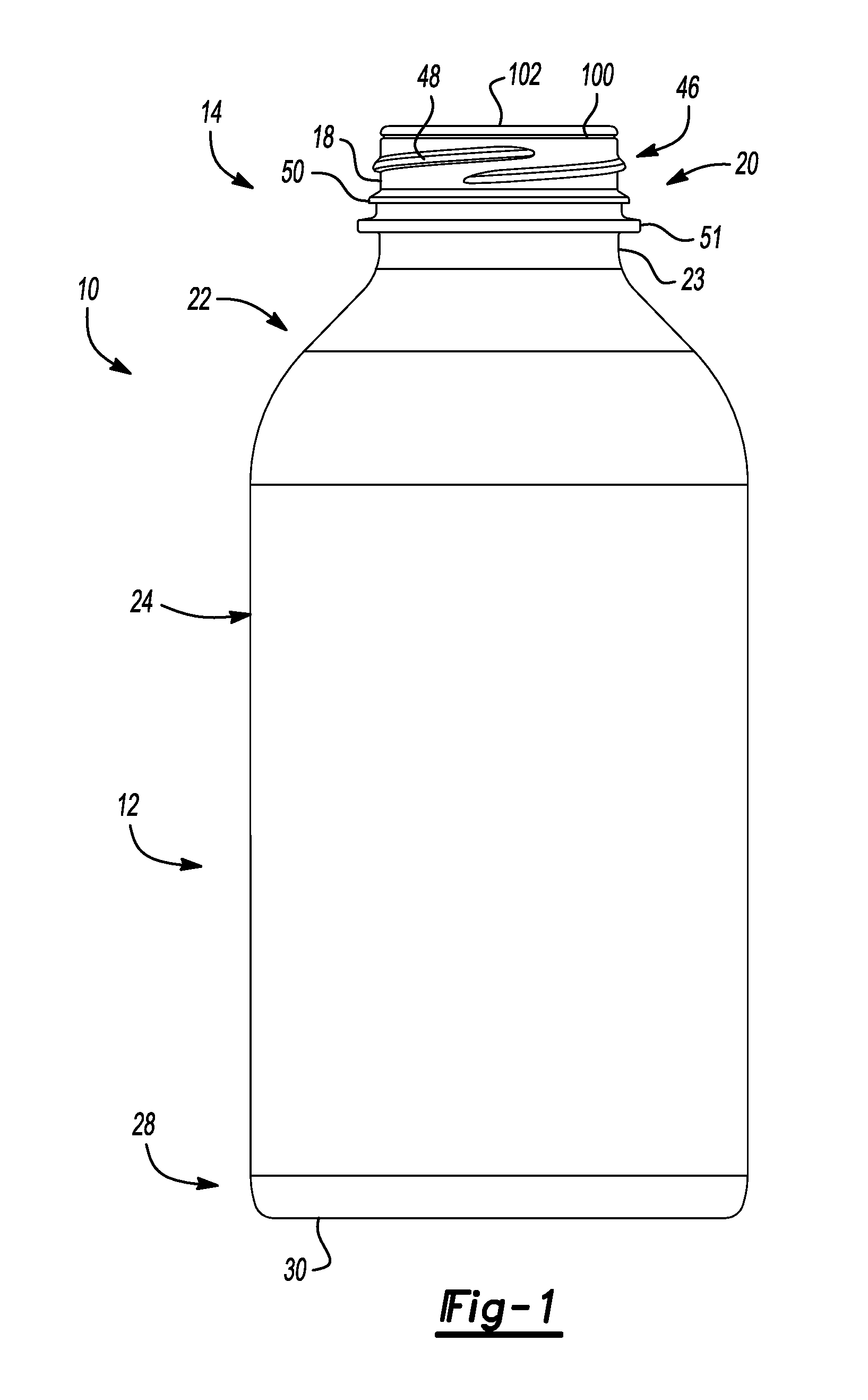
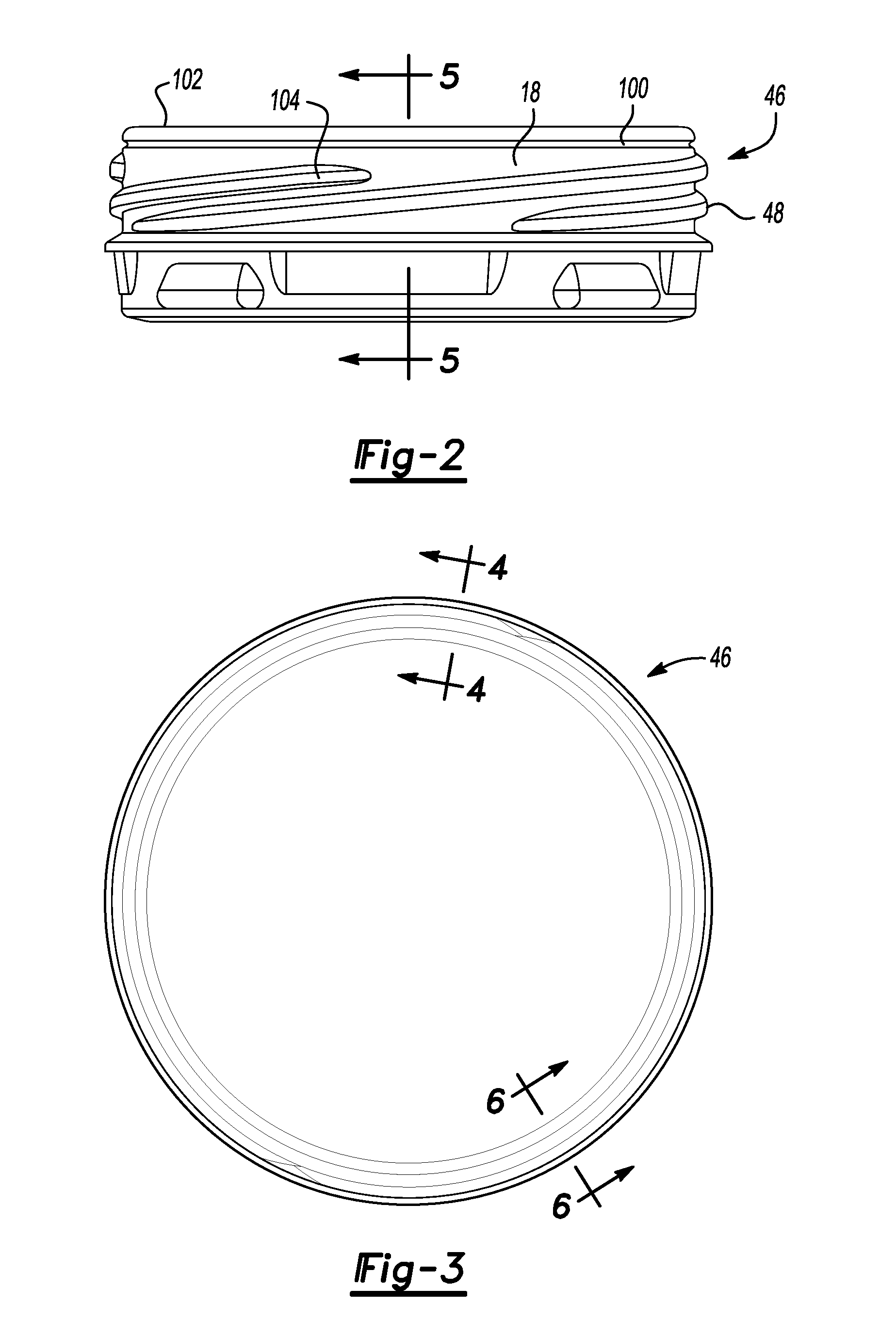
[0023]Example embodiments will now be described more fully with reference to the accompanying drawings. Example embodiments are provided so that this disclosure will be thorough, and will fully convey the scope to those who are skilled in the art. Numerous specific details are set forth such as examples of specific components, devices, and methods, to provide a thorough understanding of embodiments of the present disclosure. It will be apparent to those skilled in the art that specific details need not be employed, that example embodiments may be embodied in many different forms and that neither should be construed to limit the scope of the disclosure.

[0024]The terminology used herein is for the purpose of describing particular example embodiments only and is not intended to be limiting. As used herein, the singular forms “a”, “an” and “the” may be intended to include the plural forms as well, unless the context clearly indicates otherwise. The terms “comprises,”“comprising,”“includ...


PUM


Abstract

A container comprising a finish, a sidewall portion extending from the finish having a thread portion and an opening formed therein, a base portion extending from the sidewall portion and enclosing the sidewall portion to form a volume therein for retaining a commodity, and an inwardly directed rib member. The inwardly directed rib member is circumferentially disposed about the finish. In some embodiments, the inwardly directed rib member is positioned between the opening of the finish and the start of the thread portion.

Description

CROSS-REFERENCE TO RELATED APPLICATIONS[0001]This application claims the benefit of U.S. Provisional Application No. 61 / 359,983, filed on Jun. 30, 2010. The entire disclosure of the above application is incorporated herein by reference.FIELD[0002]This disclosure generally relates to containers for retaining a commodity, such as a solid or liquid commodity. More specifically, this disclosure relates to a container having optimized horizontal ribs disposed about a finish of the container.BACKGROUND AND SUMMARY[0003]This section provides background information related to the present disclosure which is not necessarily prior art. This section also provides a general summary of the disclosure, and is not a comprehensive disclosure of its full scope or all of its features.[0004]As a result of environmental and other concerns, plastic containers, more specifically polyester and even more specifically polyethylene terephthalate (PET) containers are now being used more than ever to package n...

Claims


Application Information

Patent Timeline
Patent Type & Authority Applications(United States)
IPC IPC(8): B65B7/28
CPCB65D1/0246Y10S215/901
Inventor MCFARLANE, RONALDPATCHEAK, TERRY D.STELZER, JAMES
Owner AMCOR RIGID PLASICS USA LLC
Learn More