Valve control apparatus and electric driving apparatus

a technology of electric driving apparatus and valve control, which is applied in the direction of mechanical equipment, operating means/releasing devices of valves, machines/engines, etc., can solve the problems of increasing manufacturing costs, unable to detect malfunctions in driving force-transmitting paths,

Inactive Publication Date: 2012-01-05
DENSO CORP
View PDF6 Cites 11 Cited by
  • Summary
  • Abstract
  • Description
  • Claims
  • Application Information

AI Technical Summary

Benefits of technology

[0018]The present invention is made in view of the above matters, and it is an object of the present invention to provide a valve control apparatus which enables to detect a malfunction with low cost.
[0019]Also, the present invention is made in view of the above matters, and it is another object of the present invention to provide an electric driving apparatus which is able to determine whether a driven member is surely moved from the unhold condition to the hold condition.
[0021]Since the valve is connected to the actuator by press-inserting the shaft into the end-gear, its manufacturing cost can be made lower.
[0025]According to the above, by detecting the rotation angle of the actuator, a malfunction in a rotation-force-transmitting path can be detected. Thus, it is unnecessary to directly detect the rotation angle of the shaft in order to find a malfunction. The manufacturing cost is not increased. A damage of a connecting portion of the shaft and the end-gear can be detected with low cost.

Problems solved by technology

That is, a malfunction in a driving-force-transmitting path can not be detected.
However, another sensor increases the manufacturing cost.
However, in this electric circuit, the change from the unhold condition to the hold condition is not determined as a normal change.

Method used


Image

  • Valve control apparatus and electric driving apparatus
  • Valve control apparatus and electric driving apparatus
  • Valve control apparatus and electric driving apparatus

Examples


first embodiment

[Operation of First Embodiment]

[0094](i) Normal condition

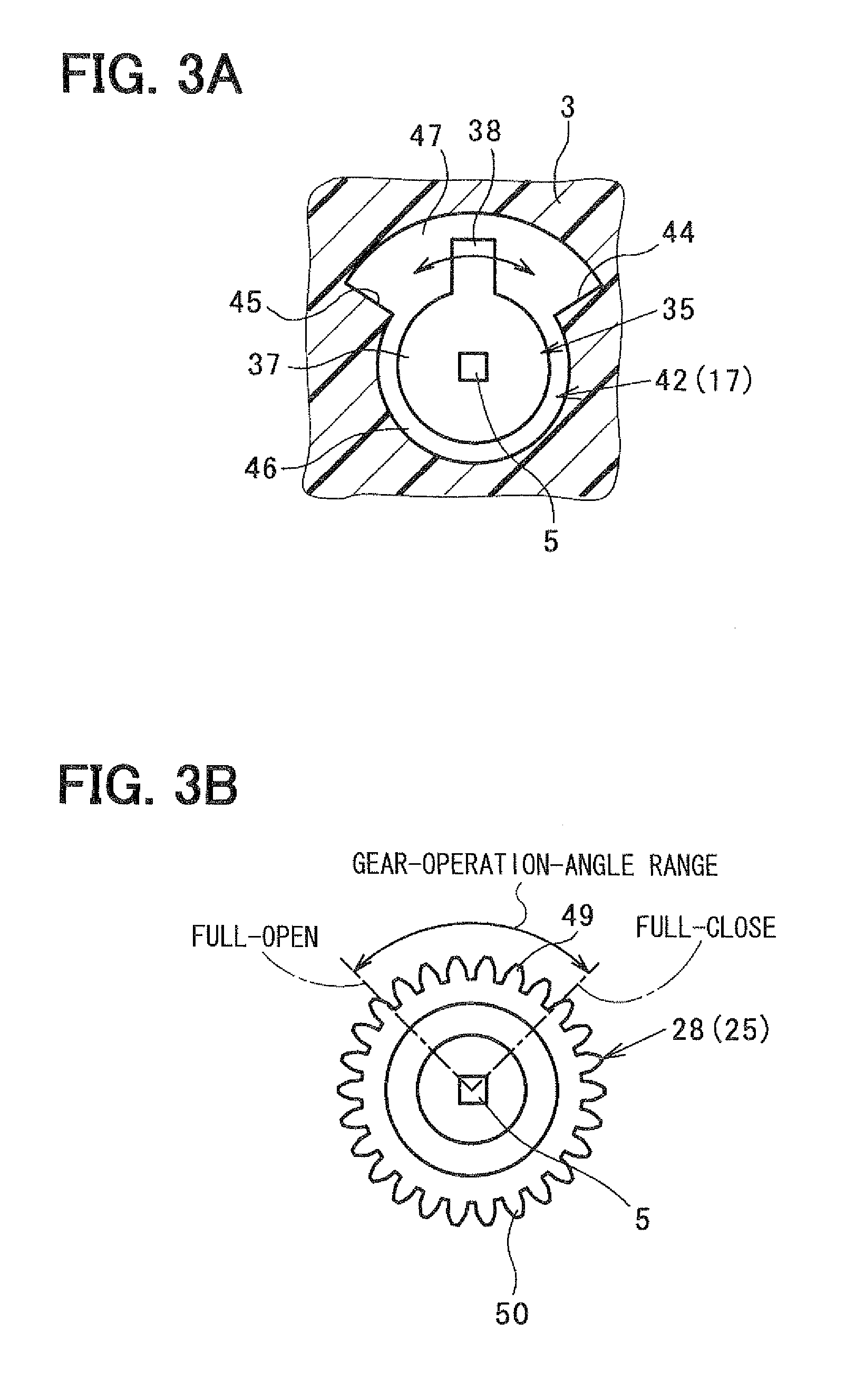
[0095]In a case that the end-gear 25 and the shaft 5 are normally connected to each other, the end-gear 25 rotates from the full-open gear position to the full-close gear position. Also, the valve 4 rotates from full-open position to the full-close position. When the stopper-contacting portion 38 is brought into contact with the full-close stopper wall 44, the valve 4 stops rotating at the full-close position. The end-gear 25 also stops at the full-close gear position.

[0096]The rotation angle sensor 7 outputs detection signals which indicate the rotation angle of the end-gear 25 is within the gear-operation-angle range. Thus, the malfunction detecting means determines that no malfunction occurs.

(ii) Abnormal condition

[0097]If the connecting portion between the end-gear 25 and the shaft 5 is broken, the end-gear 25 rotates over the full-close gear position. The end-gear 25 rotates free without respect to the full-close stopper ...

second embodiment

[0103]Referring to FIGS. 4A and 4B, a second embodiment will be described. In the second and the successive embodiments, the same parts and components as those in the first embodiment are indicated with the same reference numerals and the same descriptions will not be reiterated.

[0104]The second embodiment is different from the first embodiment in the configuration of the stopper. That is, stop-screws 58 are provided on step-surfaces 57 between the first small chamber 46 and the second small chamber 47. A tip end of the stop-screw 58 functions as a full-close position stopper 44, and a tip end of the other stop-screw 58 functions as a full-open position stopper 45.

[0105]In the second embodiment, the gear portion 28 has gear teeth partially along its circumferential periphery, as shown in FIG. 4B. That is, the inside gear teeth 49 are provided in the gear-operation-angle range, and the outside gear teeth 50 are provided at both sides of the inside gear teeth 49. The second embodiment...

third embodiment

[0106]Referring to FIG. 5, a third embodiment will be described. The third embodiment is different from the first embodiment in the configuration of the stopper and the stopper portion 35. The stopper portion 35 is comprised of a disc portion 37 and a concave portion 59. At circumferential both ends of the concave portion 59, step portions 60 are formed.

[0107]The inner diameter of the small chamber 42 is slightly larger than the outer diameter of the disc portion 37. A projection 61 is formed on an inner wall surface of the small chamber 42 in such a manner as to project toward the concave portion 59. One side surface of the projection 61 functions as the full-open position stopper 45, and the other side surface of the projection 61 functions as the full-close position stopper 44. These step portions 60 and stoppers 44, 45 regulate the operation angle range of the shaft 5. The third embodiment has the same advantages as the first embodiment.

[Modification]

[0108]The rotation angle sen...


PUM


Abstract

A valve control apparatus is provided with a valve, a shaft supporting the valve, an end-gear of an actuator driving the valve. The shaft is press-inserted into the end-gear. A stopper disposed on the shaft regulates a valve operation range. The end-gear can engage with the middle gear of the reduction-gears mechanism even in out of the gear-operation-angle range. When a rotation angle sensor detects a rotation angle of the end-gear in out of the gear-operation-angle range, it is determined that a malfunction occurs in a rotation-force-transmitting path.

Description

CROSS-REFERENCE TO RELATED APPLICATION[0001]This application is based on Japanese Patent Applications No. 2010-149284 filed on Jun. 30, 2010, and No. 2010-160184 filed on Jul. 15, 2010, the disclosures of which are incorporated herein by reference.FIELD OF THE INVENTION[0002]The present invention relates to a valve control apparatus including a valve and an actuator. The valve opens / closes a fluid-passage and the actuator drives the valve. Especially, the valve control apparatus is used for opening / closing an intake passage communicating with a combustion chamber of an internal combustion engine. Further, the present invention relates to an electric driving apparatus which drives a driven member by use of a driving force of an electric motor.BACKGROUND OF THE INVENTION[0003]Conventionally, a valve control apparatus has a valve which opens / closes an intake passage communicating with a combustion chamber of an internal combustion engine, a shaft supporting the valve, and an actuator d...

Claims


Application Information

Patent Timeline
Patent Type & Authority Applications(United States)
IPC IPC(8): F16K31/44F16K31/02
CPCF02B31/06F02B2275/48F02D11/107F02D2200/0404F16K31/047H02P29/00Y02T10/146F16K37/0041F16K31/043F16K31/046Y02T10/125Y02T10/12
Inventor HAYASHI, HIDEKIUDA, TOSHIAKI
Owner DENSO CORP
Why Eureka
Try Eureka