
Image coding apparatus, image coding method, program, and integrated circuit

a technology of image coding and coding apparatus, applied in the field of image coding apparatus and image coding method, can solve the problems of difficult to perform display while seamlessly switching between 3d video and 2d video, and above conventional techniques

Inactive Publication Date: 2012-01-05
PANASONIC CORP
View PDF2 Cites 14 Cited by
  • Summary
  • Abstract
  • Description
  • Claims
  • Application Information

AI Technical Summary

Benefits of technology

[0009]The techniques described in Patent Literatures 1 and 2 are techniques of switching between 3D video and 2D video when displaying video, and cannot switch between 3D video and 2D video and perform coding when recording video. For example in the case of coding 3D video and streaming the coded 3D video, it is desirable to switch between 3D video and 2D video at the time of coding so as to prevent eye fatigue, rather than switching between 3D video and 2D video on the display side.
[0040]The image coding apparatus and the image coding method according to the present invention can record stereoscopic video partially as 2D video so as to enable display to be performed while seamlessly switching between 3D video and 2D video.FURTHER INFORMATION ABOUT TECHNICAL BACKGROUND TO THIS APPLICATION

Problems solved by technology

However, the above conventional techniques have the following problems.
The technique described in Patent Literature 3 stores 3D video and 2D video in separate files, which makes it difficult to perform display while seamlessly switching between 3D video and 2D video.

Method used


Image

  • Image coding apparatus, image coding method, program, and integrated circuit
  • Image coding apparatus, image coding method, program, and integrated circuit
  • Image coding apparatus, image coding method, program, and integrated circuit

Examples


embodiment 1

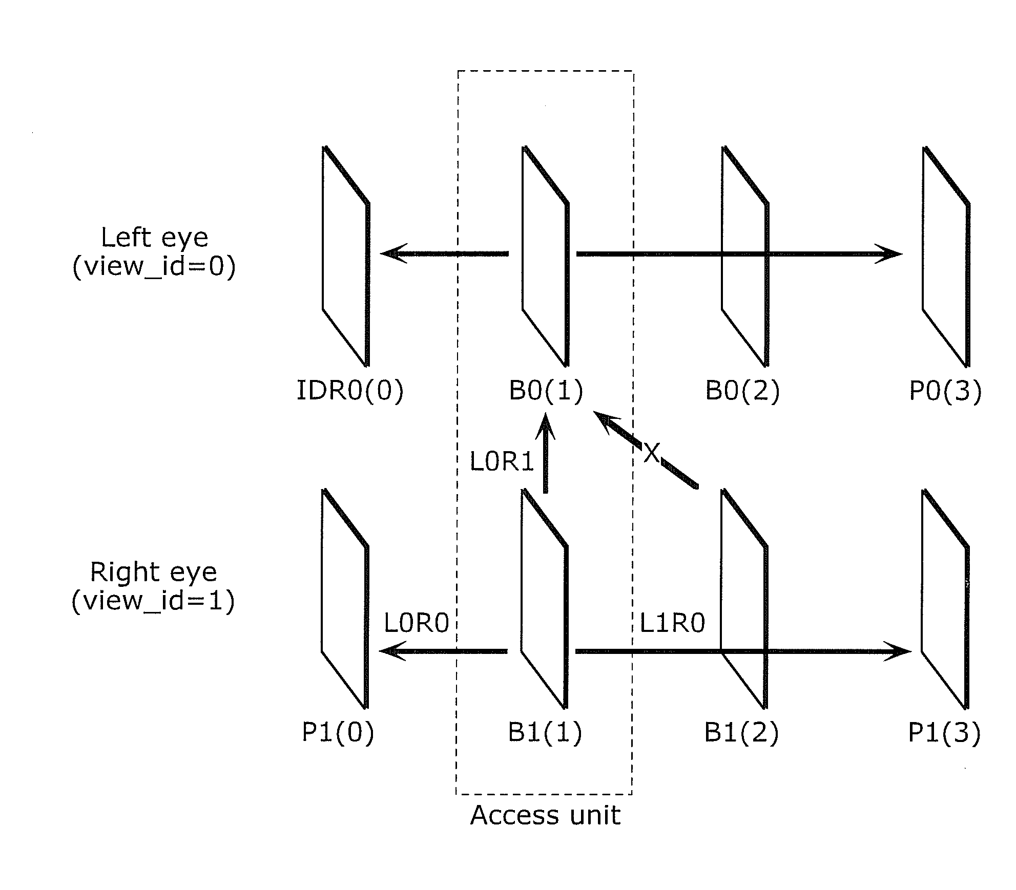
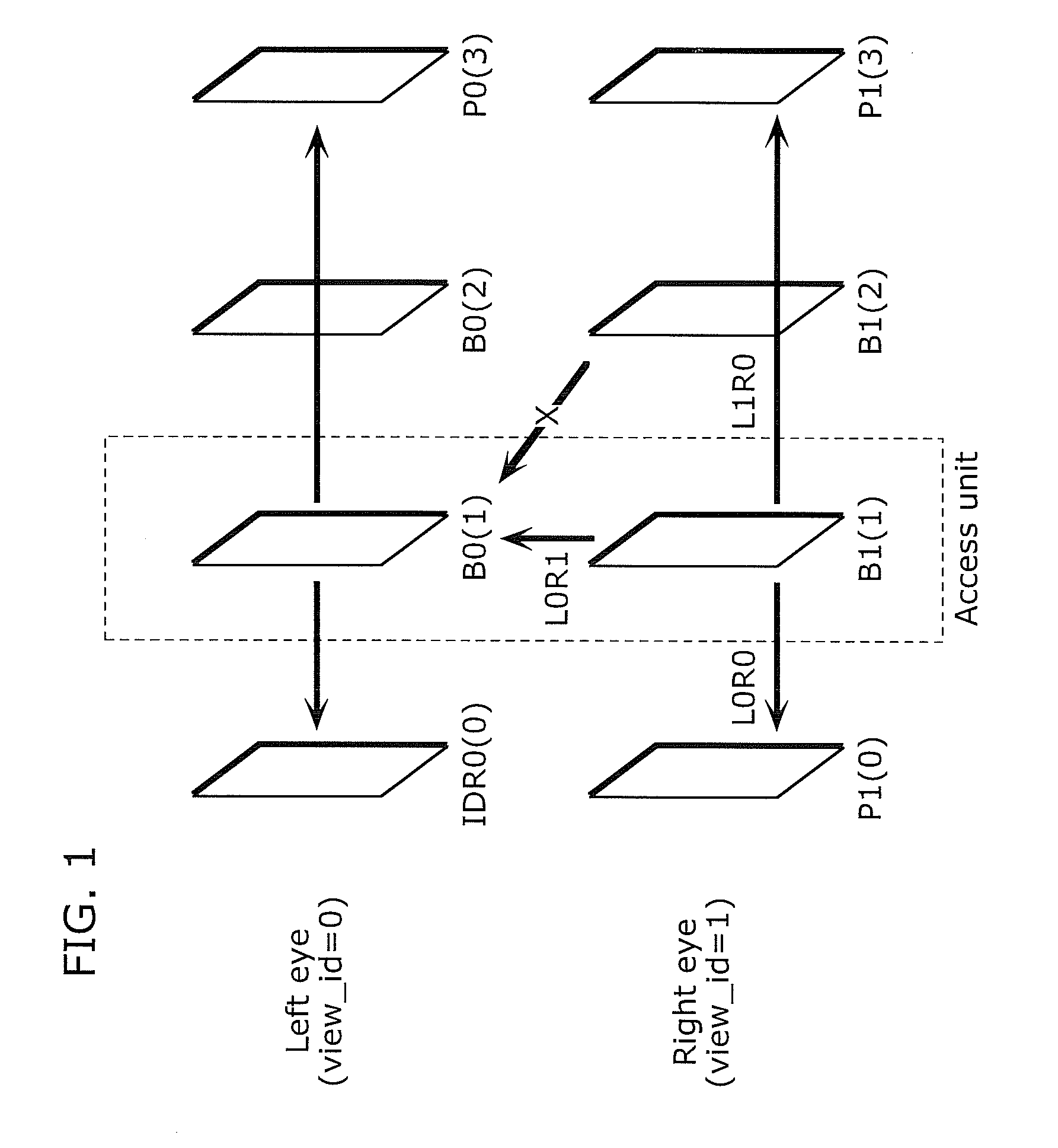
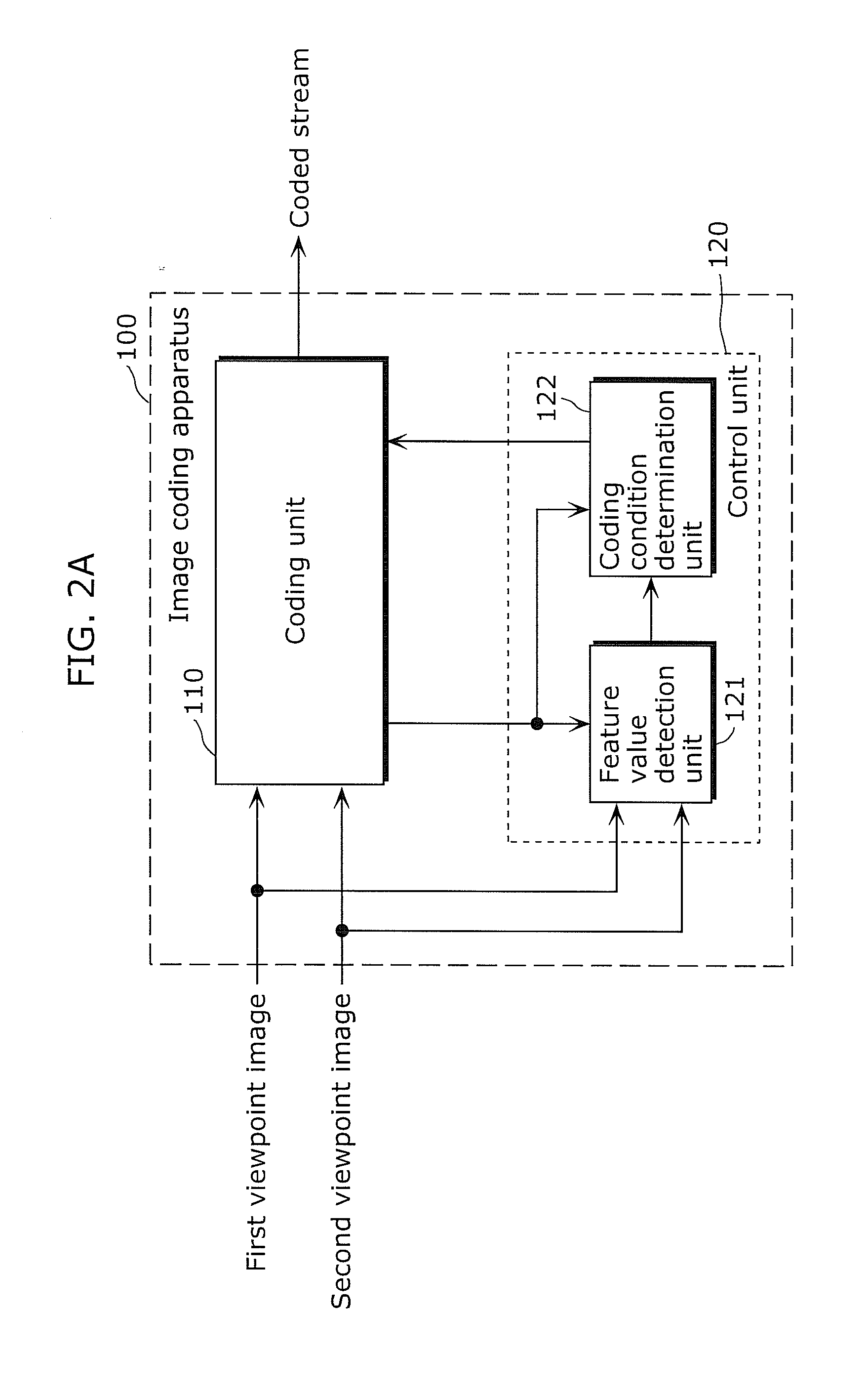
[0066]An image coding apparatus according to Embodiment 1 is an image coding apparatus that codes stereoscopic video. The image coding apparatus according to Embodiment 1 includes: a control unit that sets a coding mode to one of a 2D coding mode and a 3D coding mode, the 2D coding mode being a mode of coding the stereoscopic video so that, when the coded stereoscopic video is decoded and displayed in 3D, the stereoscopic video is displayed as 2D video, and the 3D coding mode being a mode of coding the stereoscopic video so that, when the coded stereoscopic video is decoded and displayed in 3D, the stereoscopic video is displayed as 3D video; and a coding unit that, in the case where the control unit switches the coding mode from the 3D coding mode to the 2D coding mode, codes the stereoscopic video according to a 3D coding standard when the coding mode is the 3D coding mode, and codes the stereoscopic video according to the 3D coding standard using a coding condition when the codin...

embodiment 2

[0119]Embodiment 2 describes another coding condition (coding parameter) for making the coded images identical to each other, using the structure described in Embodiment 1. The same premise as in Embodiment 1 also applies to Embodiment 2. The following describes a coding condition determination process in the case of determining to code the first viewpoint image and the second viewpoint image as a 2D image. Since other operations are the same as those in Embodiment 1, their description is omitted.

[0120]When setting the coding mode to the 2D coding mode, i.e. when determining to code the first viewpoint image and the second viewpoint image as a 2D image, the image coding apparatus according to Embodiment 2 sets the coding type of all macroblocks included in the second viewpoint image to a skip macroblock in the case where the picture type of the second viewpoint image is a P picture. In the case where the picture type of the second viewpoint image is a B picture, on the other hand, t...

embodiment 3

[0136]Embodiment 3 describes another coding condition (coding parameter) for making the coded images identical to each other, using the structure described in Embodiment 1. The same premise as in Embodiment 1 also applies to Embodiment 3. The following describes a coding condition determination process in the case of determining to code the first viewpoint image and the second viewpoint image as a 2D image. Since other operations are the same as those in Embodiment 1, their description is omitted.

[0137]When setting the coding mode to the 2D coding mode, i.e. when determining to code the first viewpoint image and the second viewpoint image as a 2D image, the image coding apparatus according to Embodiment 3 sets the first viewpoint image not only in the reference index 0 in the first reference list but also in the reference index 0 in the second reference list and sets the coding type of all macroblocks included in the second viewpoint image to a skip macroblock, in the case where the...


PUM


Abstract

An image coding apparatus records stereoscopic video partially as 2D video so as to enable display to be performed while seamlessly switching between 3D video and 2D video, and includes: a control unit that sets one of a 2D coding mode and a 3D coding mode which are modes of coding the stereoscopic video so that, when displayed in 3D, the stereoscopic video is displayed as 2D video and 3D video respectively; and a coding unit that, in the case where the control unit switches from the 3D coding mode to the 2D coding mode, codes the to stereoscopic video according to a 3D coding standard in the 3D coding mode, and codes the stereoscopic video according to the 3D coding standard using a coding condition in the 2D coding mode, the coding condition being a condition for causing the stereoscopic video to be viewed as the 2D video when displayed.

Description

BACKGROUND OF THE INVENTION[0001](1) Field of the Invention[0002]The present invention relates to an image coding apparatus and an image coding method, and in particular relates to an image coding apparatus and an image coding method that code three-dimensional (3D) video stereoscopically perceived by a viewer.[0003](2) Description of the Related Art[0004]Multiview Video Coding (MVC) is a standard developed as an extension of H.264. MVC is employed as a method of recording 3D video on Blu-ray Discs and displaying the 3D video, and its application to a format of capturing and recording 3D video by camcorders and the like is currently under study.[0005]It is considered that viewing 3D video tends to cause more eye fatigue than viewing normal two-dimensional (2D) video. Especially in the case where a displayed object has a large amount of left-right disparity, a pop-out effect increases, which tends to cause eye fatigue. Eye fatigue also tends to be caused in the case where the object ...

Claims


Application Information

Patent Timeline
IPC IPC(8): H04N13/00H04N13/02H04N19/12H04N19/134H04N19/136H04N19/139H04N19/159H04N19/172H04N19/176H04N19/196H04N19/50H04N19/597
CPCH04N9/8227H04N13/0055H04N2013/0081H04N19/137H04N19/105H04N19/196H04N19/107H04N19/597H04N13/189
Inventor OHGOSE, HIDEYUKIURANO, KATSUKIABE, KIYOFUMIARAKAWA, HIROSHIMARUYAMA, YUKIKOBAYASHI, YUKI
Owner PANASONIC CORP
Learn More