Apparatus and method for transmitting and receiving mbs data

a multicast broadcast service and data technology, applied in the field of relay stations, mobile stations, broadcast transmission systems, broadcast service distribution, etc., can solve the problems of mbs receiving apparatuses served by mbs transmitting apparatuses, >2/b> cannot recognize whether the zone #b>2, can not recognize whether, and achieve the effect of reducing bandwidth was

Inactive Publication Date: 2012-01-05
ELECTRONICS & TELECOMM RES INST
View PDF4 Cites 7 Cited by
  • Summary
  • Abstract
  • Description
  • Claims
  • Application Information

AI Technical Summary

Benefits of technology

[0018]An aspect of the present invention provides a zone allocation information providing method capable of reducing waste of the bandwidth.
[0019]Furthermore, another aspect of the present invention provides a method in which an MBS transmitting apparatus can clearly transmit information of a MIMO region to an MBS receiving apparatus although multiple zones are allocated to a non-MBS.

Problems solved by technology

However, the MBS receiving apparatus served by the MBS transmitting apparatus belonging to only the zone #1 cannot recognize whether the zone #2 has been allocated to the non-MBS region.
Furthermore, the MBS receiving apparatus served by the MBS transmitting apparatus belonging to only the zone #2 cannot recognize whether the zone #1 has been allocated to the non-MBS region.
Accordingly, waste of the bandwidth may not be avoided.
Furthermore, although the feedback information is transmitted, an MBS transmitting apparatus may not use channel information included in a feedback message.
The OL method is applied to an MBS receiving apparatus moving at high speed because channels for the MBS receiving apparatus have a severe change and thus channel information included in feedback information is difficult to be reliable.
According to the method using zone allocation information and a zone flag, however, the MBS transmitting apparatus belonging to only the zone #1 cannot allocate subbands, belonging to the zone #2, to the MIMO region because it cannot allocate the zone #2 to the non-MBS region.
Furthermore, the MBS transmitting apparatus belonging to only the zone #2 cannot allocate any subband, belonging to the zone #1, to a region for MIMO because it cannot allocate the zone #1 to a non-MBS region.

Method used


Image

  • Apparatus and method for transmitting and receiving mbs data
  • Apparatus and method for transmitting and receiving mbs data
  • Apparatus and method for transmitting and receiving mbs data

Examples


first embodiment

[0071]In a first embodiment in which allocation information of the MIMO region is transmitted, an MBS transmitting apparatus may transmit information of the number of subbands, allocated to the MIMO region, as region allocation information. Furthermore, the MBS receiving apparatus recognizes subbands not allocated to an MBS region, from among the number of subbands transmitted from a first subband, as subbands allocated to the MIMO region.

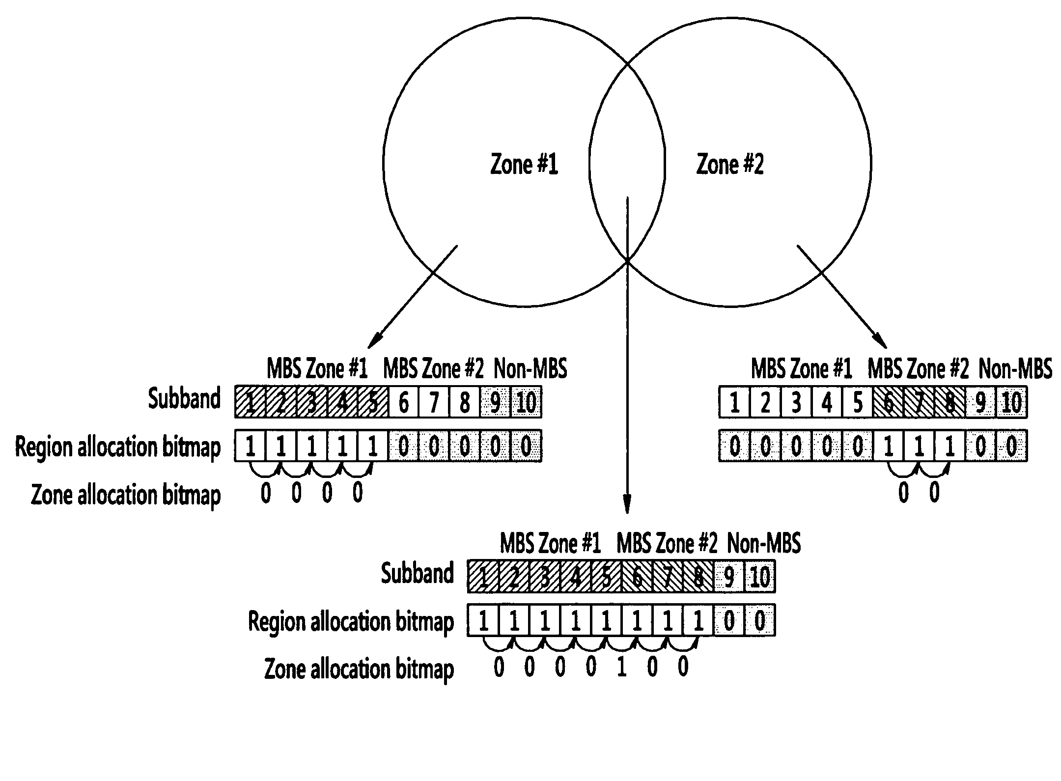
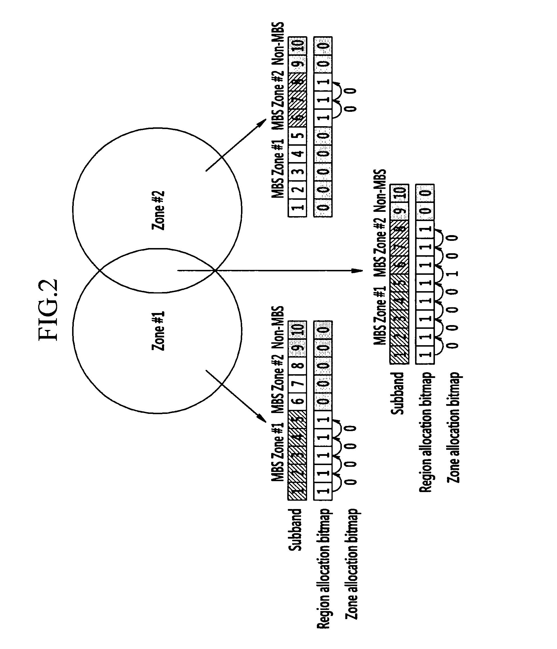
[0072]For example, in a system such as that of FIG. 2, an MBS transmitting apparatus may transmit 9 as the number of subbands allocated to the MIMO region. In this case, since an MBS transmitting apparatus belonging to both the MBS zone #1 and the MBS zone #2 allocates the subbands 1 to 8 to the MBS region, an MBS receiving apparatus served by the MBS transmitting apparatus recognizes only the subband 9 as a subband allocated to the MIMO region. Since an MBS transmitting apparatus belonging to only the MBS zone #1 allocates the subbands 1 to 5 to t...

second embodiment

[0073]In a second embodiment in which allocation information of a MIMO region is transmitted, an MBS transmitting apparatus may transmit the indices of subbands allocated to the MIMO region, from among subbands not allocated to an MBS region. More particularly, the MBS transmitting apparatus may transmit the indices of the subbands, allocated to the MIMO region, through a bitmap. Here, the number of bits of the bitmap is the same as the number of subbands not allocated to the MBS region, and the bits corresponds to respective subbands not allocated to the MBS region. Furthermore, each bit indicates whether a corresponding subband is allocated to a unicast-based MIMO region.

[0074]For example, in a system, such as that of FIG. 2, an MBS transmitting apparatus belonging to both the MBS zone #1 and the MBS zone #2 may transmit a bitmap including two bits, an MBS transmitting apparatus belonging to only the MBS zone #1 may transmit a bitmap including 5 bits, and an MBS transmitting appar...

third embodiment

[0075]In a third embodiment in which allocation information of a MIMO region is transmitted, an MBS transmitting apparatus may transmit information of the number of subbands allocated to a MIMO region or a bitmap including the predetermined number of bits, as region allocation information. Here, the number of bits of the bitmap is the same as the number of subbands allocated to the non-MBS region by means of a network in a carrier through which MBS is transmitted. The bits corresponds to respective subbands as many as the number of bits of the bitmap from first subband, from among the number of subbands allocated to the non-MBS region. Furthermore, each bit indicates whether a corresponding subband is allocated to a unicast-based MIMO region.

[0076]If an MBS transmitting apparatus transmits information of the number of subbands allocated to the MIMO region, an MBS receiving apparatus recognizes subbands corresponding to the number of subbands transmitted by the MBS transmitting appar...


PUM


Abstract

An MBS transmitting apparatus allocates a plurality of subbands of an MBS transmission carrier to an MBS region and a non-MBS region and generates region allocation information of the MBS region and the non-MBS region. The MBS transmitting apparatus allocates the subbands, allocated to the MBS region, to at least one MBS zone and generates MBS zone allocation information of the at least one MBS zone. The MBS transmitting apparatus transmits the region allocation information and the MBS zone allocation information and transmits MBS data through the subbands allocated to the MBS region.

Description

CROSS-REFERENCE TO RELATED APPLICATION[0001]This application claims priority to and the benefit of Korean Patent Application No. 10-2010-0061347 filed in the Korean Intellectual Property Office on Jun. 28, 2010, 10-2010-0065731 filed in the Korean Intellectual Property Office on Jul. 8, 2010 and 10-2011-0062843 filed in the Korean Intellectual Property Office on Jun. 28, 2011, the entire contents of which are incorporated herein by reference.BACKGROUND OF THE INVENTION[0002](a) Field of the Invention[0003]The present invention relates to a base station, a relay station, and a mobile station. More particularly, the present invention relates to a method and apparatus for sending and receiving Multicast Broadcast Service (MBS) data.[0004](b) Description of the Related Art[0005]In a mobile communication system using a multi-carrier, data transmitted through one carrier supporting MBS may be divided into a plurality of subbands on the frequency axis. All subbands may be allocated to an M...

Claims


Application Information

Patent Timeline
Patent Type & Authority Applications(United States)
IPC IPC(8): H04W4/06
CPCH04W4/02H04W48/08H04W4/06H04W4/021H04W72/30
Inventor KIM, EUNKYUNGJUNG, SOOJUNGCHA, JAE SUNCHANG, SUNG CHEOLLEE, HYUNYOON, CHUL SIK
Owner ELECTRONICS & TELECOMM RES INST
Why Eureka
Try Eureka