Devices and method for accelerometer-based characterization of cardiac synchrony and dyssynchrony

a technology of accelerometer and cardiac synchrony, which is applied in the field of accelerometer-based characterization of cardiac synchrony and dyssynchrony, can solve the problems of prior disclosures not providing devices or methods for identifying the optimal myocardial pacing zone or region, and prior disclosures not providing methods for multiple catheter repositioning

Inactive Publication Date: 2012-01-05
CARDIOSYNC
View PDF1 Cites 92 Cited by
  • Summary
  • Abstract
  • Description
  • Claims
  • Application Information

AI Technical Summary

Benefits of technology

[0031]In one embodiment, the invention employs an acceleration sensor to characterize displacement and vibrational LV motion, and uses this motion data to characterize the different phases of the LV cycle for analyzing LV function. In another embodiment, the invention measures acceleration in at least two different frequencies with either two or more sensors or two or more frequency filters to characterize LV motion. In yet another embodiment, the invention senses high frequency (greater than about 150 Hz) low amplitude motion related to valvular pathology (e.g., mitral regurgitation), mid frequency (between about 20 Hz and 150 Hz) lower amplitude motion related to isovolumic contraction / relaxation and valve closure, and low frequency (less than about 20 Hz) high amplitude motion signals related to displacement of the LV occurring during the ejection phase and early and late diastole. In still a further embodiment, the invention identifies a target pacing region or regions in the LV or RV using an acceleration sensor by localizing regions of late onset of motion relative to the QRS, or isovolumic contraction, or mitral valve closure, or by pacing of target regions and measuring LV function in response to pacing. In another embodiment, the invention measures myocardial motion with an accelerometer relative to the onset of isovolumic relaxation or aortic valve closure to determine contractile reserve and / or the presence of post-systolic shortening. In yet another embodiment, the invention identifies target pacing regions in the LV using an acceleration sensor by pacing different regions and measuring the regional and / or global LV functional response to pacing. In still a further embodiment, the invention uses an acceleration sensor to measure LV function by sensing changes in the time interval length of the LV cardiac cycle phases (isovolumic contraction / relaxation, ejection, and / or filling); changes in mitral regurgitation signal amplitude and duration; and changes in peak amplitude and slope of isovolumic contraction, isovolumic relaxation, and ejection phases; and frequency changes of the isovolumic contraction and relaxation phases. In another embodiment, the invention may use an acceleration sensor to identify patients with LV dyssynchrony or asynchrony and a normal QRS width (90-120 ms), a modestly increased QRS width (120 to 150 ms), and wide QRS or LBBB pattern (QRS>150 ms). In yet another embodiment, the invention facilitates identification of the coronary ostium and LV vein branches into the coronary sinus for cannulation with guidewires or catheters. In a still further embodiment, the invention provides the physician with data from acceleration sensing for management of optimal pharmacologic treatment. In yet another embodiment, the invention provides a wireless acceleration sensing medical device and system for assessing LV motion and function.
[0033]In one illustrative system, the accelerometer sensors are micro-electromechanically (“MEM”s)-based to allow miniaturization, low-power consumption, and multiple-axis sensing. The sensors are conductively attached to the subcutaneously-implanted data acquisition and processing device, which is capable of RF telemetry communication and data transfer. The IAD monitors both vibrational and displacement LV motion during systole and diastole in at least the longitudinal axis. The IAD may also monitor LV acceleration in at least one location near the mitral annulus.
[0034]In another illustrative system, the IAD is integrated with a CRT device with a multi-electrode LV pacing lead. The IAD monitors LV motion and can dynamically adjust the electrodes that are used to pace. Similarly, the IAD can be integrated with or used with a CCM device to help monitor mechanical function and optimize therapy.
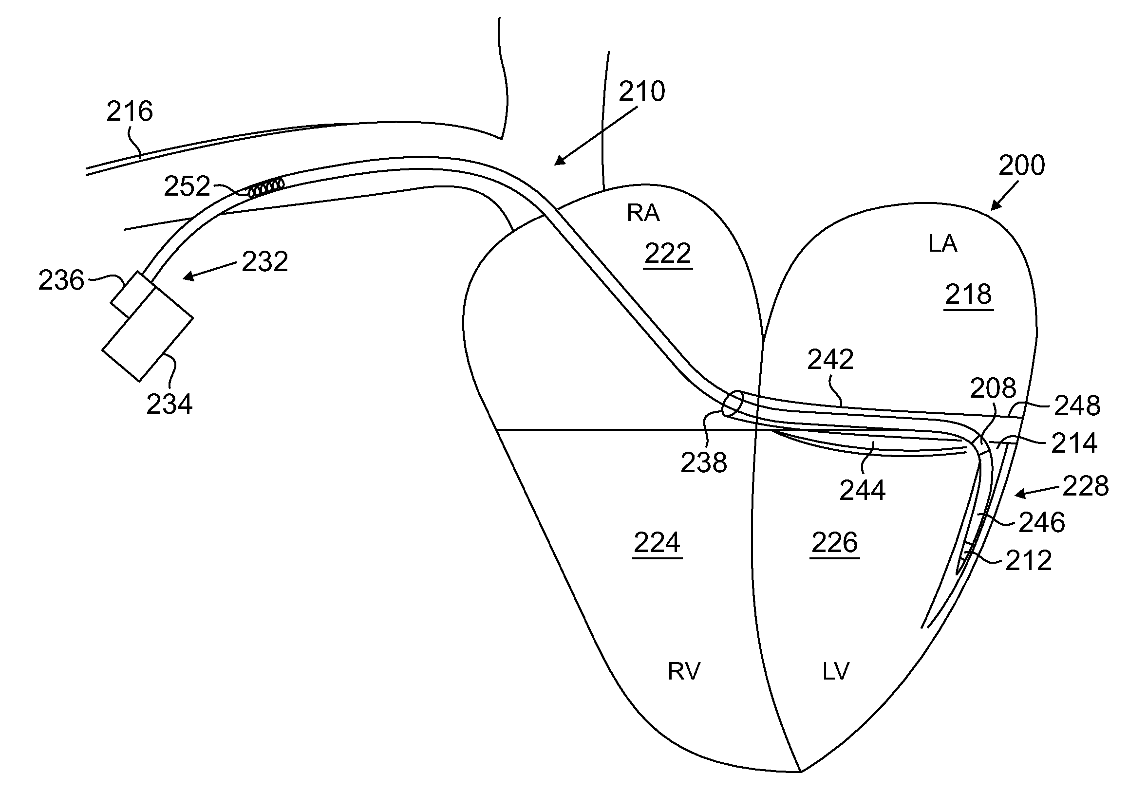
[0039]In still another embodiment, an LV motion mapping system is disclosed which can sense LV motion for optimizing CRT lead placement. The system may include an LV venous catheter, LV lead, guidewire, or guide catheter / catheter system with an acceleration sensor, connected to a signal processing and powering module, and a graphical display. The acceleration sensing catheter may be moved to different locations in the LV and used to identify regions of late systolic or post-systolic motion relative to a reference point such as the QRS, valve closures, or isovolumic contraction / relaxation. Alternatively, a pacing catheter or guidewire may be moved to different LV locations and an acceleration sensing catheter near the mitral annulus may measure changes in LV function due to pacing. Both techniques may be used to optimize CRT LV lead implantation. The mapping system may also be used to determine optimal RV pacing sites which may mitigate the need for placing an LV CRT lead.
[0041]Monitoring changes in the frequency of the vibrational component of the ICP may be more practical and accurate than measuring amplitude changes for assessing cardiac function. Similarly, monitoring the time interval of this phase may prove more practical and accurate. Such an approach would reduce the sensitivity of the acceleration signal measurement and the interpretation of this measurement to the effects of gravity, sensor axis orientation, relative motion of the sensing device to which the sensor is affixed, and translational motion of the heart.

Problems solved by technology

These disclosures do not provide a means for separating out the displacement and vibrational components of LV motion, which occur at the same time, through different frequency sensing or filtering and analysis.
Prior disclosures do not provide devices or methods for identifying the optimal myocardial pacing zone or region in the left or right ventricle for CRT, such as measuring the onset of motion relative to the onset of the QRS or isovolumic contraction or mitral valve closure.
Prior disclosures do not provide a method for multiple catheter repositionings in the LV or coronary sinus or great cardiac vein to map the motion of the LV for identifying the optimal pacing region.
Prior disclosures also do not disclose measuring cardiac pathologies such as mitral regurgitation, which may be sensed as vibration motion at frequencies greater than about 150 Hz.
Prior disclosures do not disclose a means for optimizing complete cardiomyopathy therapy, including drugs and devices, through the use of implantable acceleration devices.
Prior disclosures do not provide a means for zeroing out gravity effects and tilt of the sensor.
Consequently, the disclosure does not provide a way to monitor information on phases of the LV cycle that characterize LV function such as, displacement related to ejection, filling, afterload, volume status, and preload, nor can the same characterize vibration related to mitral regurgitation.
Also, neither disclosure nor device design is provided that would allow characterization of myocardial strain and strain rate.
Similar to the above, this disclosure generally describes interventricular interval optimization and does not provide a means for intraventricular target pacing region identification.
Further, there is no disclosure for multi sensor integration into the same lead catheter, guidewire, or guide catheter / catheter system, and analysis of acceleration at different frequencies.

Method used


Image

  • Devices and method for accelerometer-based characterization of cardiac synchrony and dyssynchrony
  • Devices and method for accelerometer-based characterization of cardiac synchrony and dyssynchrony
  • Devices and method for accelerometer-based characterization of cardiac synchrony and dyssynchrony

Examples


Embodiment Construction

[0103]Acceleration sensors are well-suited for measuring both vibration and displacement motions. They can be oriented along an appropriate axis to maximize the motion signal and to accurately measure the displacement. An acceleration sensor placed in or on the heart can measure vibrational or displacement components of heart motion, or both thereby allowing the characterization of pumping function and various pathologies.

[0104]The sensor may be based on MEMs principles, which allows for miniaturization and low power consumption. The design and fabrication of capacitance MEMs-based accelerometers are known to those skilled in the art. MEMs-based accelerometers are typically fabricated from silicon or semiconductor substrates. In one illustrative system, the sensor is fabricated from a radiation-resistant semiconductor as the sensor will be implanted in many cases under fluoroscopic guidance. The general design of the accelerometer measures capacitance changes due to the movement of ...


PUM


Abstract

Systems and methods according to the invention employ an acceleration sensor to characterize the synchrony or dyssynchrony of the left ventricle. Patterns of acceleration related to myocardial contraction can be used to assess synchrony or dyssynchrony. Time-frequency transforms and coherence are derived from the acceleration. Information and numerical indices determined from the acceleration time frequency transforms and coherence can be used to find the optimal pacing location for cardiac resynchronization therapy. Similarly, the information can be used to optimize timing intervals including V to V and A to V timing.

Description

REFERENCE TO CONTINUING APPLICATIONS[0001]This application is a divisional of U.S. application Ser. No. 11 / 789,434, filed Apr. 24, 2007 entitled Devices And Methods For Accelerometer-Based Characterization Of Cardiac Synchronizing And Dyssynchrony, which claims the benefit of U.S. Provisional Patent Application Ser. No. 60 / 794,632, filed Apr. 24, 2006, expired. This application also claims the benefit of priority of U.S. Provisional Patent Application Ser. No. 60 / 835,171, filed Aug. 1, 2006, expired; U.S. Provisional Patent Application Ser. No. 60 / 839,494, filed Aug. 22, 2006, expired. Furthermore, this application is a continuation in part of U.S. Ser. No. 12 / 337,581, filed Dec. 17, 2008 which is a continuation of Ser. No. 11 / 347,623, filed Feb. 3, 2006, abandoned, which claims the benefit of priority of U.S. Provisional Application 60 / 680,673, filed May 13, 2005, expired; Provisional Application 60 / 677,569, filed May 4, 2005, expired; Provisional Application 60 / 669,324, filed Apr....

Claims


Application Information

Patent Timeline
Patent Type & Authority Applications(United States)
IPC IPC(8): A61B5/0205A61B5/0402A61B5/0245
CPCA61B5/0031A61B5/6876A61B5/0422A61B5/0452A61B5/0456A61B5/11A61B5/1102A61B5/726A61B7/00A61B2562/028A61N1/3627A61B5/6851A61B5/6852A61B5/6862A61B5/6869A61B5/021A61B5/287A61B5/352A61B5/349A61B5/355
Inventor DOBAK, III, JOHN DANIEL
Owner CARDIOSYNC
Why Eureka
Try Eureka