Spinal needle including a chamber for identifying cerebrospinal fluid

a cerebrospinal fluid and spinal needle technology, applied in the field of spinal needle including a chamber for cerebrospinal fluid, can solve the problems of potential risk of toxicity, inability to perforate the dura mater, and medical techniques entail some risks for patients

Inactive Publication Date: 2012-01-05
VELEZ RIVERA HECTOR DE JES S
View PDF12 Cites 18 Cited by
  • Summary
  • Abstract
  • Description
  • Claims
  • Application Information

AI Technical Summary

Problems solved by technology

Such medical techniques entail some risks for patients; for such reason, taking into account the main parts of the human body involved in these procedures is important, such as meninges and cerebrospinal fluid that protect the central nervous system.
Nevertheless, a problem remains in epidural anesthesia since dura mater and arachnoid layers are so close together that sometimes perforating of the dura mater is not possible without piercing through the arachnoid layer.
Furthermore, there is a potential risk of toxicity caused by large doses of medicament, unnecessary to achieve a proper blockade.
However, both the projections and the window are very small and the visual detection of CSF through the needle is not always achieved.
In fact, in some instances, small air bubbles gather below

Method used


Image

  • Spinal needle including a chamber for identifying cerebrospinal fluid
  • Spinal needle including a chamber for identifying cerebrospinal fluid
  • Spinal needle including a chamber for identifying cerebrospinal fluid

Examples


Embodiment Construction

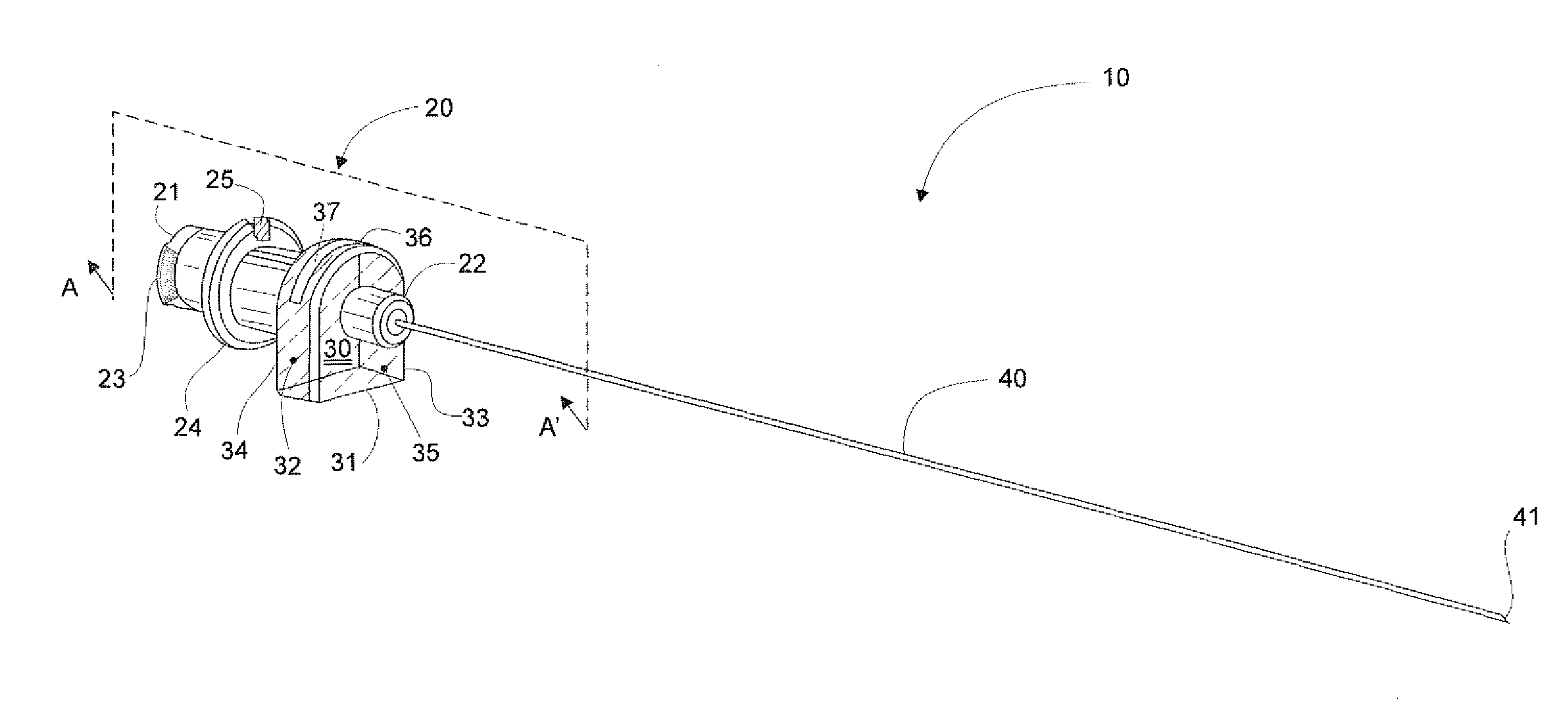
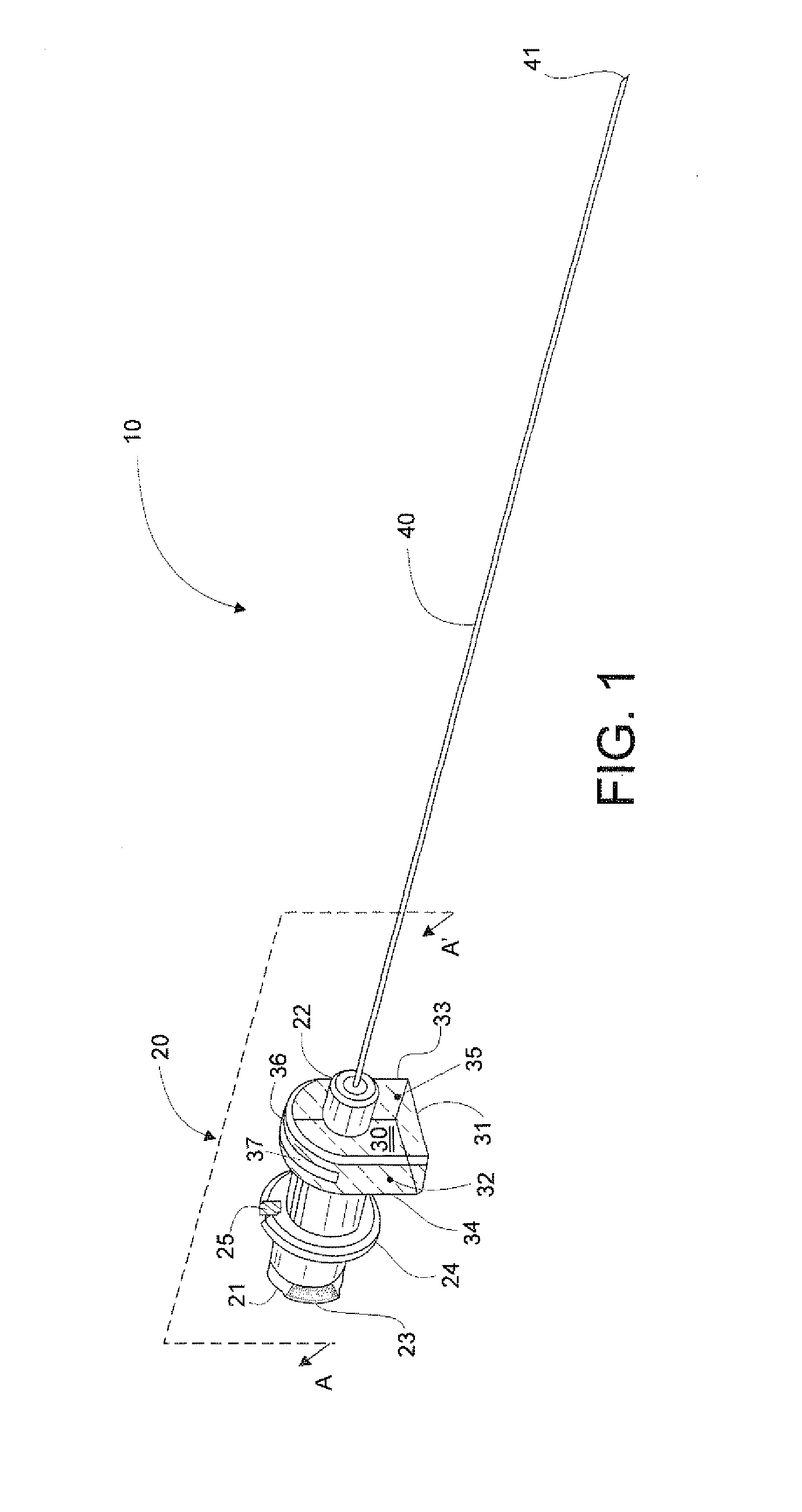
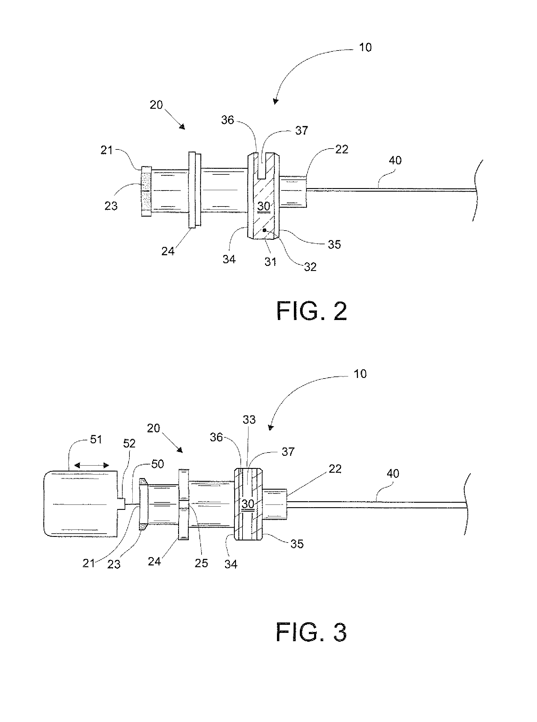
[0026]Referring to FIGS. 1 to 4, there is shown therein a spinal needle with a chamber for the CSF, the needle being identified with number 10 and employed during epidural and spinal surgical procedures. The spinal needle with chamber 10 is designed according to the principles of a first preferred embodiment of the present invention, which is to be considered as illustrative rather than limiting thereof. In FIGS. 2 and 3, the distal end of the spinal needle 10 is not shown for clarity purposes. According to medical practice, the distal direction is that closer to the patient, whereas proximate direction is that oriented towards the physician.

[0027]From FIGS. 1 to 4, it can be seen that the spinal needle 10 comprises three main elements, the first one is a fastening member 20 that allows a user to hold the needle 10 with the fingers; the second element is a chamber 30 that receives a small amount of CSF that, according to the preferred embodiment, has a capacity of about 0.001 to app...


PUM


Abstract

Disclosed herein is a spinal needle for epidural and spinal anesthesia and analgesia. The needle is formed by three main elements: the first one is a fastening member which allows the user to grab the needle with the fingers; the second element is a chamber that receives an amount of cerebrospinal fluid (CSF); and the third element of the spinal needle is a cannula in fluid communication with the chamber and further attached to the fastening member. The chamber is preferably transparent in order to readily detect the presence of CSF inside the needle. In a preferred embodiment, the chamber has a bottom wall that supports the needle in its entirety. The fastening member and the chamber comprise tactile markings with the same orientation as that of the tip of the cannula, to become aware of the direction in which the anesthetic will be supplied.

Description

FIELD OF THE INVENTION[0001]The present invention relates to the techniques applied in the designing of devices and equipment for surgical procedures, and more specifically, to a spinal needle including a chamber for cerebrospinal fluid (CSF), wherein the chamber is useful to detect the presence of CSF during anesthesia and analgesia procedures, among other surgical operations.BACKGROUND OF THE INVENTION[0002]There exist two basic techniques for introducing medicaments into a patient's spinal area, namely epidural and spinal; these techniques can be employed to create spinal anesthesia or analgesia. In these types of surgical procedures, an anesthetic is injected in the spinal cord and in the nerve roots in order to block pain sensations from one region of the body, such as the abdomen, hips, legs, or pelvis during delivery.[0003]Such medical techniques entail some risks for patients; for such reason, taking into account the main parts of the human body involved in these procedures ...

Claims


Application Information

Patent Timeline
IPC IPC(8): A61M5/00
CPCA61B2017/00455A61B17/3401
Inventor VELEZ-RIVERA, HECTOR DE JES S
Owner VELEZ RIVERA HECTOR DE JES S
Why Eureka
Try Eureka