

Power transmission device for vehicle
a technology for power transmission devices and vehicles, which is applied in hybrid vehicles, gearing, transportation and packaging, etc., can solve the problems of increasing the number of clutches and the size of the entire power transmission devi
- Summary
- Abstract
- Description
- Claims
- Application Information
AI Technical Summary
Benefits of technology
Problems solved by technology
Method used
Image

Examples
first embodiment
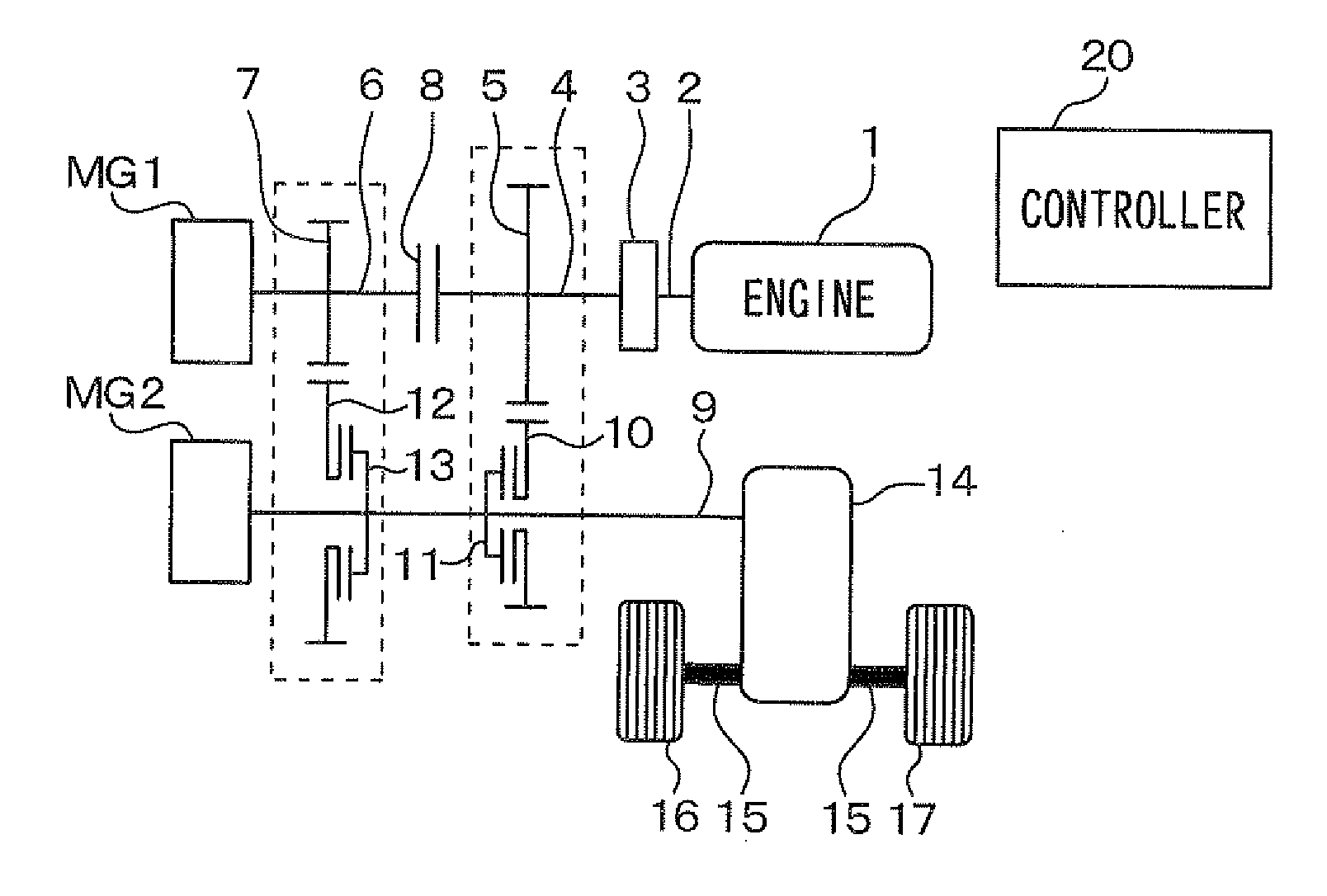
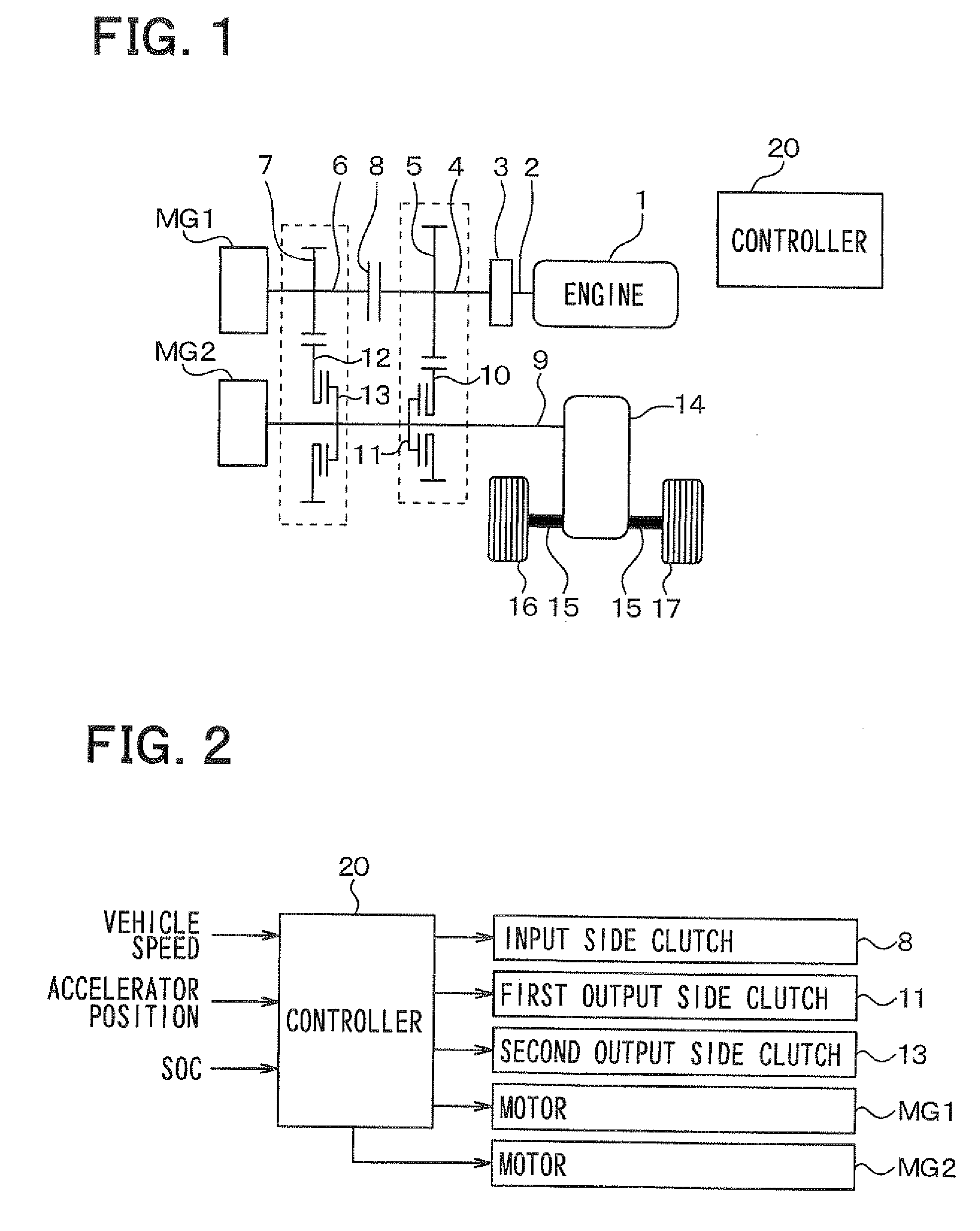
[0068]Hereinafter, a first embodiment of the present invention will be described with reference to the drawings. FIG. 1 is a skeleton diagram showing a construction of a vehicular power transmission device according to the first embodiment. The vehicular power transmission device according to the present embodiment is mounted to a hybrid vehicle. The vehicular power transmission device has an engine 1, motors MG1, MG2, a first engine input shaft 2, a damper 3, a second engine input shaft 4, a first drive gear 5, a first motor input shaft 6, a second drive gear 7, an input side clutch 8, an output shaft 9, a first driven gear 10, a first output side clutch 11, a second driven gear 12, a second output side clutch 13, and a differential gear 14. The vehicular power transmission device transmits powers (i.e., driving torque) generated by the engine 1 and the motors MG1, MG2 to an axle 15, thereby generating driving forces in driving wheels 16, 17.
[0069]The engine 1 is an internal combus...
second embodiment
[0151]Next, a second embodiment of the present invention will be described, focusing on differences from the first embodiment. As shown in FIG. 13, differently from the first embodiment, in the vehicular power transmission device according to the present embodiment, the input side clutch 8 that engages and disengages the first motor input shaft 6 and the second engine input shaft 4 is arranged between the motor MG1 and the second drive gear 7, not between the first drive gear 5 and the second drive gear 7.
[0152]In order to realize such the arrangement, a cylindrical motor input shaft 18 is attached to a portion of the input side clutch 8 that rotates with the first motor input shaft 6. The cylindrical motor input shaft 18 coaxially surrounds another portion of the input side clutch 8 that rotates with the second engine input shaft 4. The cylindrical motor input shaft 18 coaxially surrounds the second engine input shaft 4 and extends toward the engine 1. The cylindrical motor input s...
third embodiment
[0156]Next, a third embodiment of the present invention will be described, focusing on differences from the first embodiment. Differently from the first embodiment, in the vehicular power transmission device according to the present embodiment, the input side clutch 8 that engages and disengages the first motor input shaft 6 and the second engine input shaft 4 is arranged between the engine 1 and the first drive gear 5 as shown in FIG. 14, not between the first drive gear 5 and the second drive gear 7.
[0157]In order to realize such the arrangement, a cylindrical engine input shaft 19 is attached to a portion of the input side clutch 8 that rotates with the second engine input shaft 4. The cylindrical engine input shaft 19 coaxially surrounds another portion of the input side clutch 8 that rotates with the first motor input shaft 6. The cylindrical engine input shaft 19 coaxially surrounds the first motor input shaft 6 and extends toward the motor MG1. The cylindrical engine input sh...
PUM
 Abstract
Description
Claims
Application Information