Turntable

Active Publication Date: 2012-01-12
MERRILL GEORGE EARNEST +1
View PDF0 Cites 2 Cited by
  • Summary
  • Abstract
  • Description
  • Claims
  • Application Information

AI Technical Summary

Benefits of technology

[0006]An improved turntable with vibration isolating properties is disclosed. This improved turntable reduces vibration through a unique plinth materia

Problems solved by technology

Turntables are susceptible to various sources of noise and vibration which are amplified along with the recorded sound, and which can interfere with the enjoyment of the recording.
The noise and vibration are “energy intrusions” that degrade the quality of sign

Method used


Image

  • Turntable
  • Turntable
  • Turntable

Examples


Embodiment Construction

[0016]The following detailed description is presented to enable any person skilled in the art to make and use the invention. For purposes of explanation, specific details are set forth to provide a thorough understanding of the present invention. However, it will be apparent to one skilled in the art that these specific details are not required to practice the invention. Descriptions of specific applications are provided only as representative examples. Various modifications to the preferred embodiments will be readily apparent to one skilled in the art, and the general principles defined herein may be applied to other embodiments and applications without departing from the scope of the invention. The present invention is not intended to be limited to the embodiments shown, but is to be accorded the widest possible scope consistent with the principles and features disclosed herein.

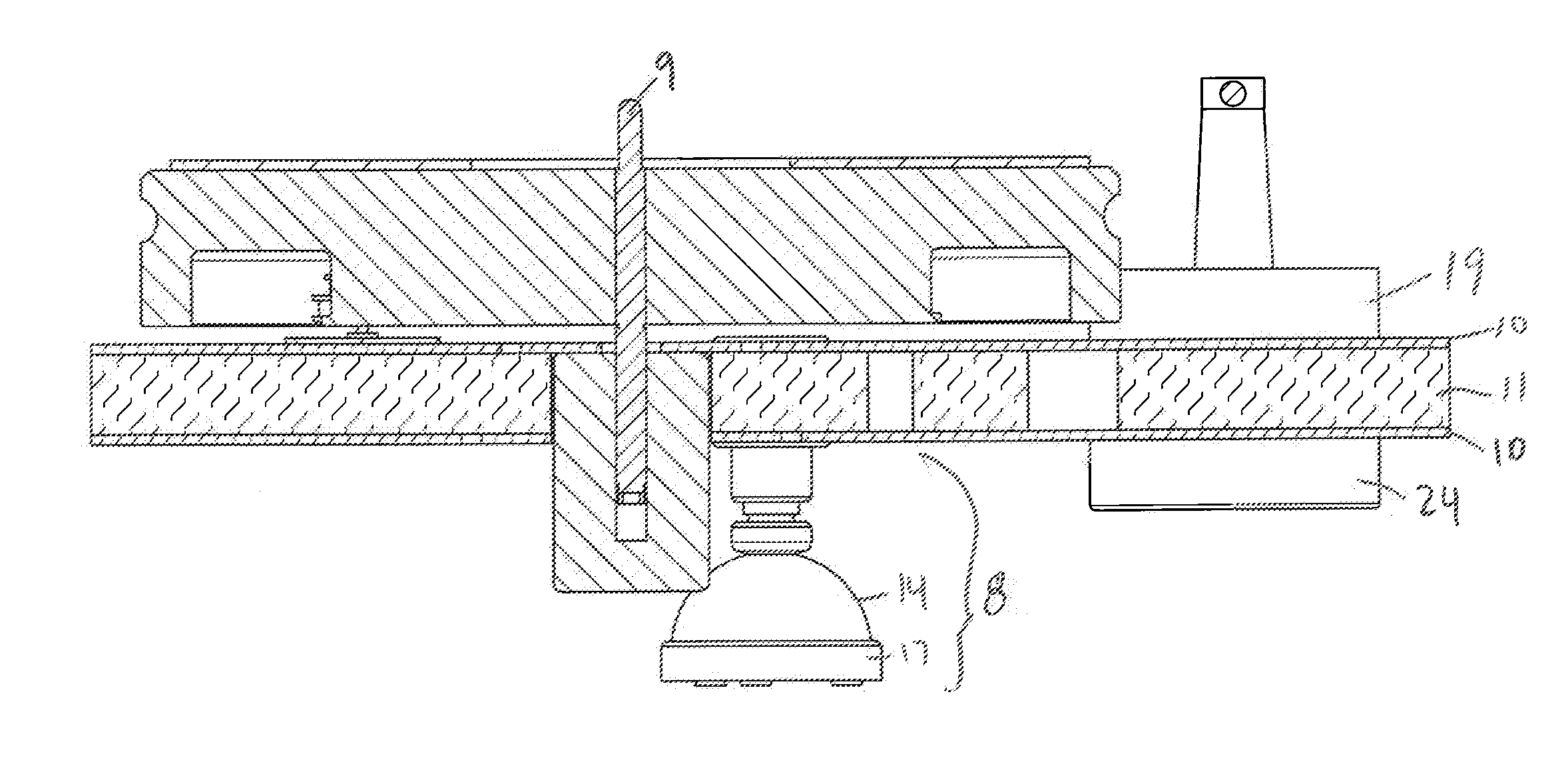
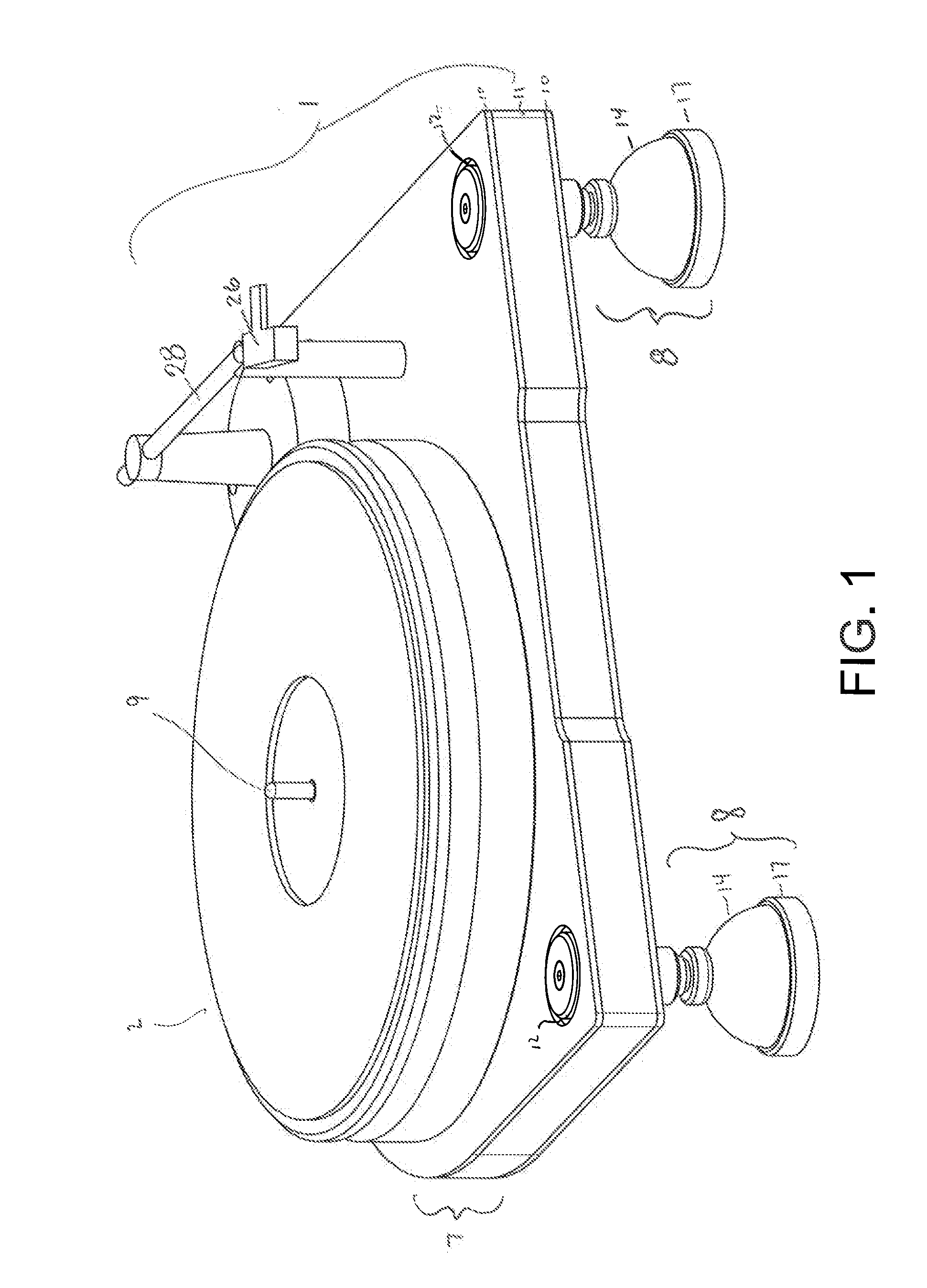
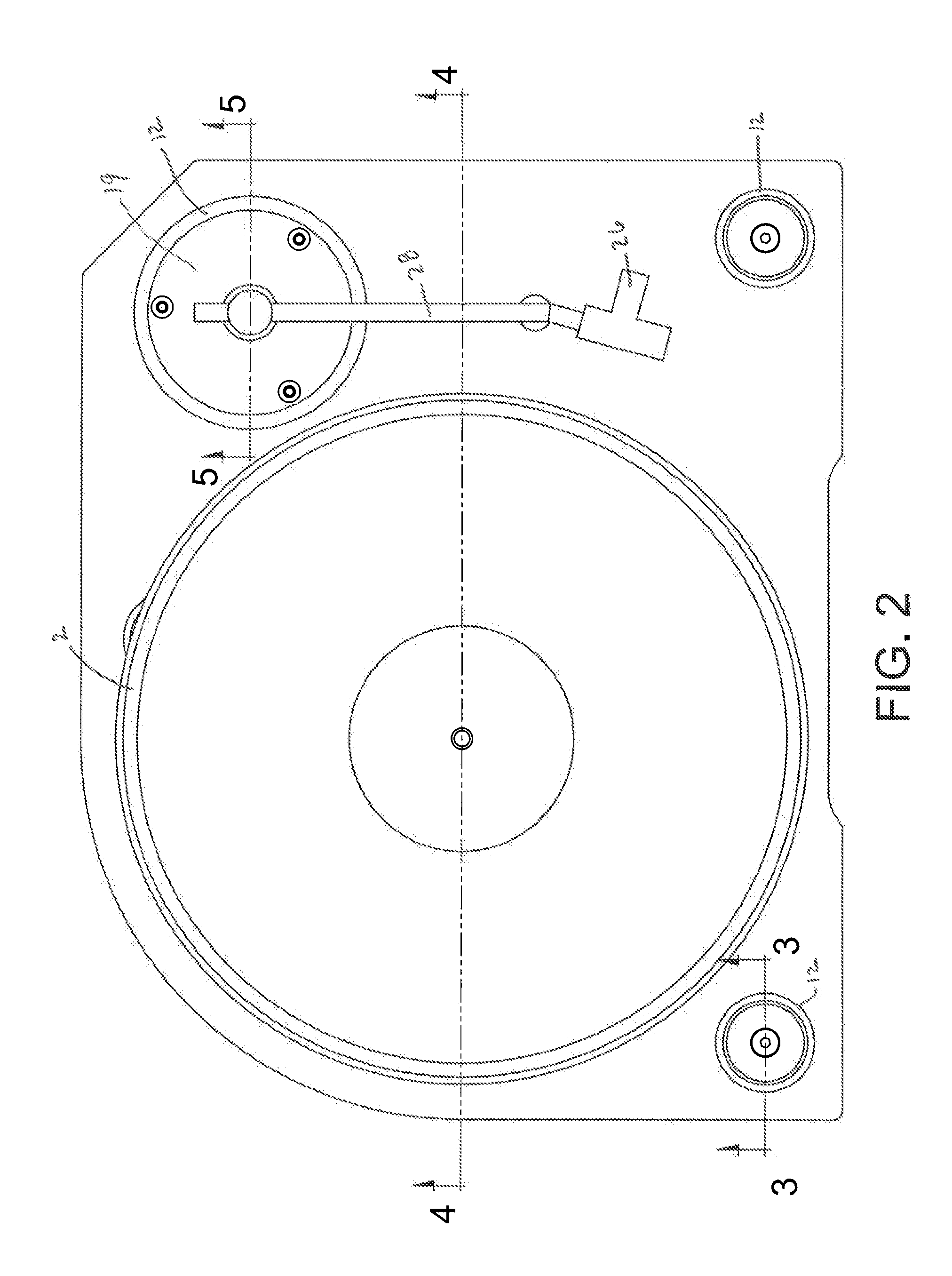
[0017]Referring to the drawings, FIG. 1 illustrates an exemplary embodiment of the improved turntable. ...


PUM


Abstract

An improved turntable is described with inherent properties for reducing noise generated by external sources or by the parts of the turntable. The plinth of the turntable is comprised of an elastomeric layer and at least one stiffening layer that adds rigidity to the plinth. The support feet, spindle bearing, and armboard only come into contact with the elastomeric layer, which dampens energy, allowing the turntable produce the audio on the record without excessive noise.

Description

CROSS-REFERENCES TO RELATED APPLICATIONS[0001]This application claims the benefit of U.S. Provisional Application No. 61 / 292,029 filed Jan. 4, 2010 and incorporated herein by reference in entirety.FIELD OF THE INVENTION[0002]The present invention is generally directed toward a new turntable with improved noise reduction properties.BACKGROUND OF THE INVENTION[0003]Turntables, also known as record players, work through the transduction of mechanical vibrations of the needle into an electrical signal which can then be amplified. Turntables are susceptible to various sources of noise and vibration which are amplified along with the recorded sound, and which can interfere with the enjoyment of the recording. The noise and vibration are “energy intrusions” that degrade the quality of signal produced by the turntable.[0004]There are three general sources of energy intrusion that affect a turntable: airborne, mechanical, and internal noise generated by the turntable itself. Airborne energy ...

Claims


Application Information

Patent Timeline
IPC IPC(8): G11B3/61G11B3/60
CPCG11B3/61
Inventor MERRILL, GEORGE EARNESTWILLIAMS, ROBERT EDWIN
Owner MERRILL GEORGE EARNEST
Why Eureka
Try Eureka