Gas pressurized separation column and process to generate a high pressure product gas

a technology of product gas and separation column, which is applied in the direction of separation process, liquid degasification, products, etc., can solve the problems of high energy consumption of conventional absorption/stripping process, and the most expensive step in an integrated carbon capture and sequestration process. achieve the effect of reducing the energy requirement and reducing the subsequent compression work

Active Publication Date: 2012-01-12
CARBON CAPTURE SCI
View PDF11 Cites 19 Cited by
  • Summary
  • Abstract
  • Description
  • Claims
  • Application Information

AI Technical Summary

Benefits of technology

[0033]It is believed that the process can reduce the energy requirement in the stripping column and produce a high pressure, pure product gas stream, which will reduce subsequent compression work.

Problems solved by technology

CO2 capture from utility flue gas is the most expensive step in an integrated carbon capture and sequestration (CCS) process.
A conventional absorption / stripping process is energy intensive.
(a) The operating pressure of the stripper is determined by vapor pressure of the CO2-lean solution in the reboiler, which in turn is determined by composition of lean solution and the reboiler temperature. In order to increase the operating pressure the temperature in the reboiler has to be raised, which is often limited by the stability of the amine solvents. The reboiler temperature in a conventional stripper is typically at 120° C. and the operating pressure is thus limited at around 28 psia.
(b) Heat required for CO2 stripping is entirely provided by water vapor generated in the reboiler. Thus, water vapor is used not only as stripping gas but also as a heat carrier. Due to the dual functions of steam PH2O and PCO2 in the stripper from bottom to top are all correlated with each other.
(c) Due to the low operating pressure (˜28 psia) of the stripper (thus low pressure of CO2 product), a large amount of compression work is required to compress the CO2 product to a pipeline transportation-ready pressure (˜2250 psia).
However, no external heat sources except heat from the reboiler were added to the stripping column and as a result, the temperature distribution within the stripper is coupled.
Therefore, the energy performance of hexane stripping system was even worse than the conventional stripping system.

Method used


Image

  • Gas pressurized separation column and process to generate a high pressure product gas
  • Gas pressurized separation column and process to generate a high pressure product gas
  • Gas pressurized separation column and process to generate a high pressure product gas

Examples


Embodiment Construction

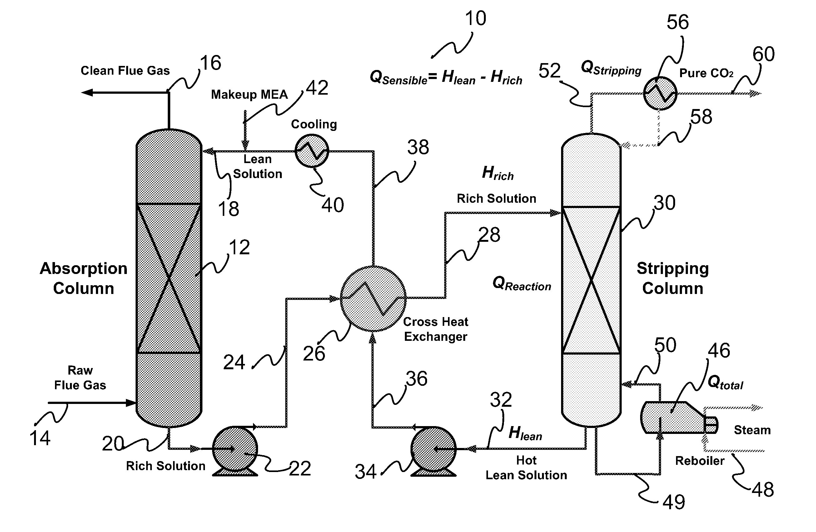
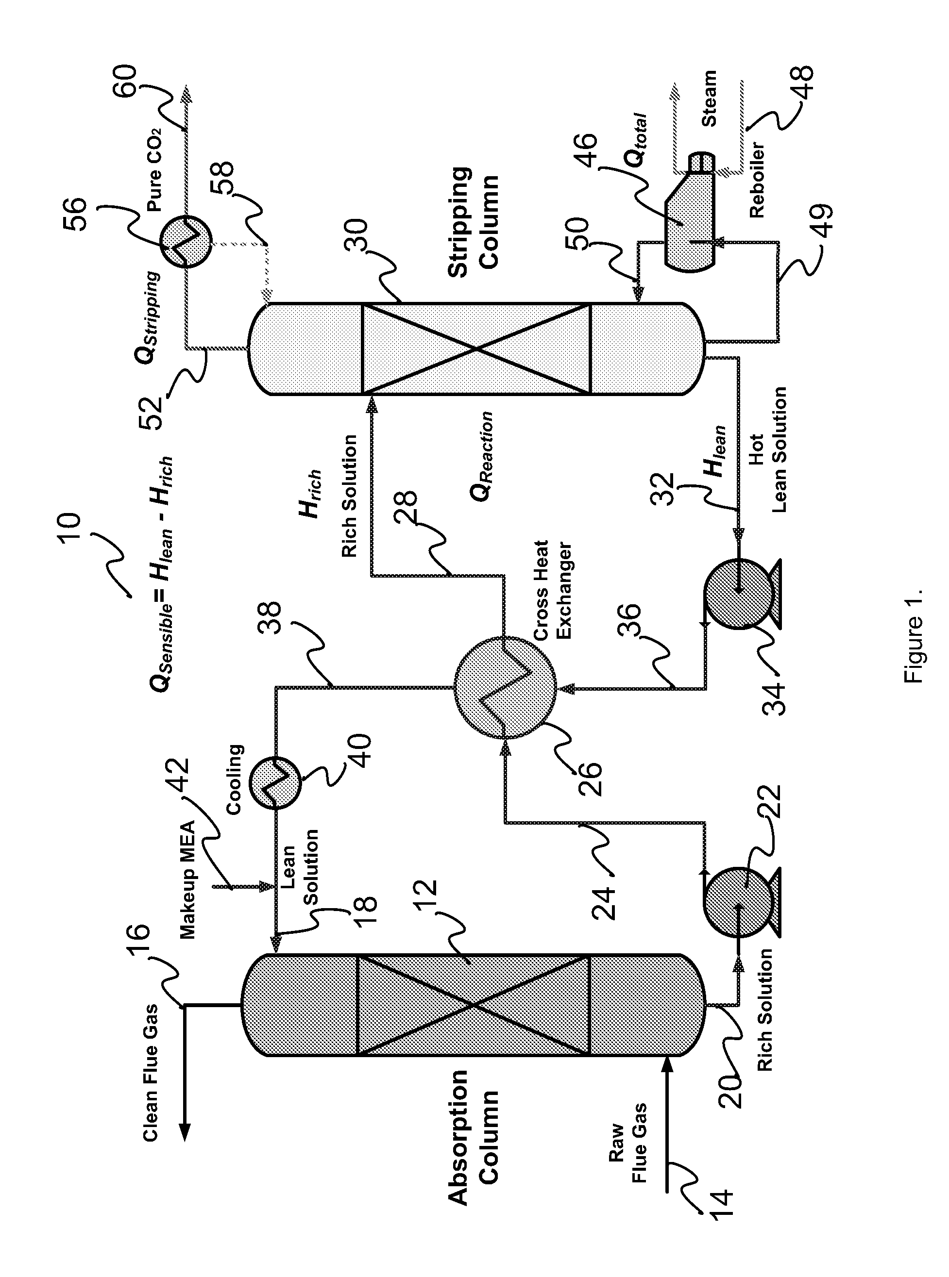
[0045]A gas pressurized separation system of the present invention comprises a gas pressurized stripping column with at least one first inlet allowing flow of one or more liquid streams in a first direction and at least one second inlet allowing flow of one or more high pressure gas streams in a second direction. The directions of each stream within the column may be the same as or different from each other, and may change with respect to each other. For example, they may be co-current (in the same direction) or counter-current (opposite directions) to each other, or anywhere between these two extremes; for example, perpendicular to each other. Also, contact between the streams may include intimate and / or turbulent mixing of the streams.

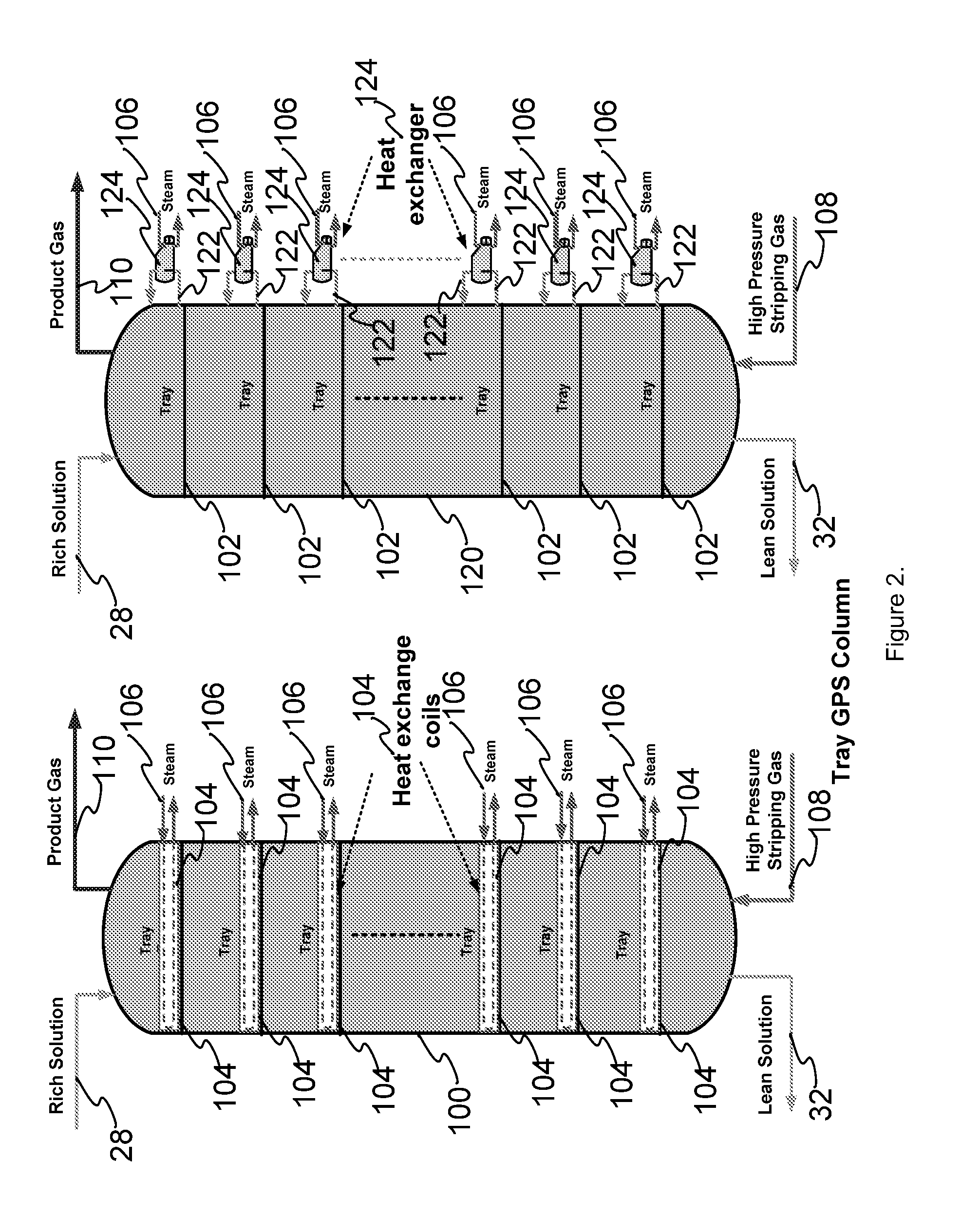
[0046]The separation column may further comprise two or more heat supplying apparatus, such as heat exchangers or heating coils, positioned in different locations along the column. The heat supplying apparatuses may be connected to each other, such a...


PUM

PropertyMeasurementUnit
pressureaaaaaaaaaa
partial pressureaaaaaaaaaa
pressureaaaaaaaaaa

Abstract

The present invention provides a gas pressurized separation system to strip a product gas from a liquid stream and yield a high pressure gaseous effluent containing the product gas. The system comprises a gas pressurized stripping apparatus, such as a column, with at least one first inlet allowing flow of one or more liquid streams in a first direction and at least one second inlet allowing flow of one or more high pressure gas streams in a second direction, to strip the product gas into the high pressure gas stream and yield through at least one outlet a high pressure gaseous effluent containing the product gas; and two or more heat supplying apparatuses provided at different locations along the column. Processes for separating a product gas from a gaseous mixture to yield a high pressure gaseous effluent containing the product gas, utilize the gas pressurized separation system described above.

Description

FIELD OF THE INVENTION[0001]The present invention relates to gas pressurized separation columns and to processes utilizing the columns.BACKGROUND OF THE INVENTION[0002]CO2 capture from utility flue gas is the most expensive step in an integrated carbon capture and sequestration (CCS) process. The current commercial state of the art of capture technology utilizes amine-based absorption technology. A typical, conventional process lousing an absorption column 12 is illustrated in FIG. 1. Raw flue gas 14 enters the absorption column 12 and clean flue gas 16 exits as described below. A CO2-lean solution 18 enters into an absorption column 12 from the top and flows downward. By contacting the flue gas countercurrent, the solution absorbs most of the CO2 in the flue gas in the absorption column 12 and produces a CO2-rich solution exiting at 20. The CO2-rich solution goes through pump 22 and in line 24 goes through heat exchanger 26. After exchanging heat with the CO2-lean solution from the...

Claims


Application Information

Patent Timeline
Patent Type & Authority Applications(United States)
IPC IPC(8): C01B31/20B01D19/00C01B32/50
CPCB01D19/0005B01D2258/0283C01B31/20Y02C10/06B01D53/1418B01D53/1425B01D53/1475B01D53/62B01D2252/20405B01D2252/20421B01D2252/20431B01D2252/20484B01D2252/20489B01D2257/504B01D19/0015C01B32/50Y02C20/40Y02P20/151
Inventor CHEN, SHIAOGUOPAN, ZIJIANG
Owner CARBON CAPTURE SCI
Why Eureka
Try Eureka