Electrical connector

a technology of electrical connectors and covering parts, applied in the direction of electrical apparatus, connection, coupling device connection, etc., can solve the problems easy warping of conventional electrical connectors, and increased production costs of warped and uneven covering parts, etc., to achieve the effect of enhancing the evenness of the fabrication process

Inactive Publication Date: 2012-01-12
TSAI HORNG YU
View PDF0 Cites 5 Cited by
  • Summary
  • Abstract
  • Description
  • Claims
  • Application Information

AI Technical Summary

Benefits of technology

[0006]The present invention provides an electrical connector with an upper base and a lower base. The upper base has no integral and downwardly-extended side plate hooking structure to be engaged with the lower base. By using an engaging structure to engage the upper base with the lower base, the upper base is engaged with the lower base and the upper base is restricted to be moved forwardly or backwardly relative to the lower base. In such way, the upper base has enhanced evenness in the fabrication process.
[0007]The present also provides an electrical connector with an engaging mechanism. The engaging mechanism is arranged on at least two outer peripheries of the upper base and the lower base to facilitate combining the upper base and the lower base together, thereby improving the engaging efficacy of the hooks of the conventional electrical connector.
[0008]The present further provides an electrical connector with an engaging structure to engage the upper base with the lower base. The upper base is made by an insulating flat plate in order to meet the requirements of small size, light weightiness and evenness.

Problems solved by technology

The conventional electrical connector, however, still has some drawbacks.
Due to the stress, the covering member 91 is readily warped and thus uneven.
As the size of the covering member 91 is gradually reduced to comply with the miniaturization requirement, the problem of producing the warped and uneven covering member will become more serious.

Method used


Image

  • Electrical connector
  • Electrical connector
  • Electrical connector

Examples


first embodiment

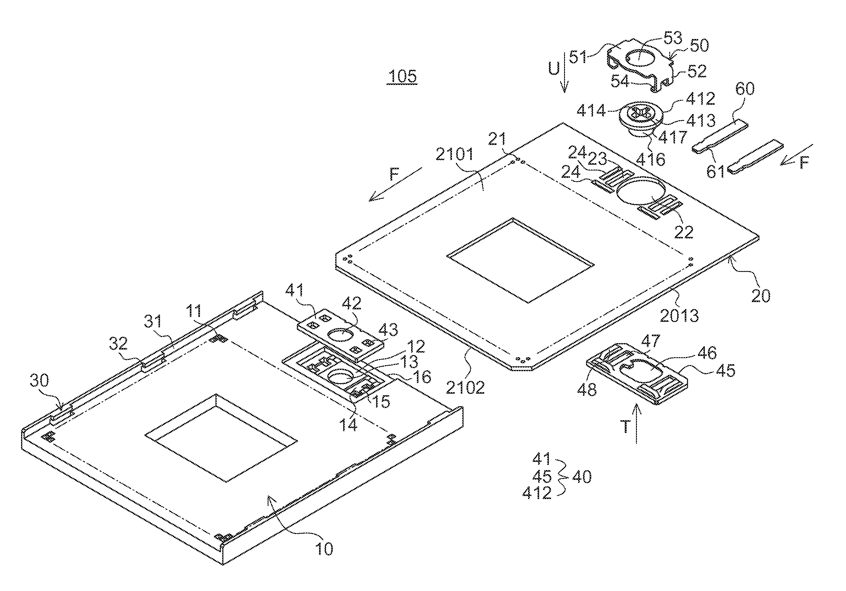
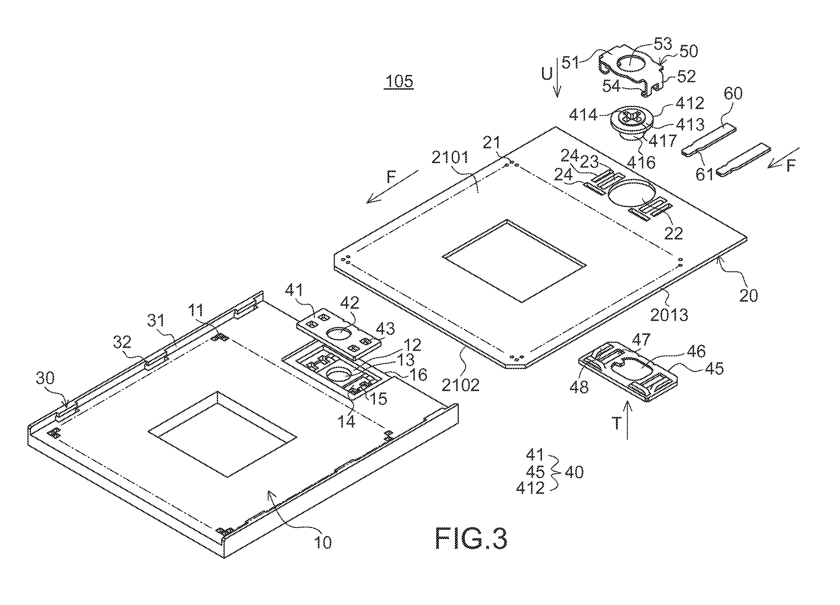
[0068]The outer periphery of the upper base 20 at least comprises an upper-base top surface 2101, an upper-base bottom surface 2102 and an upper-base sidewall 2103. The upper-base sidewall 2103 is arranged between the upper-base top surface 2101 and the upper-base bottom surface 2102. The upper base 20 comprises multiple rows of insertion holes 21, which are arranged in an array. For clarification and brevity, only the insertion holes 21 disposed at the corners of the upper base 20 are shown. These insertion holes 21 correspond to the terminal slots 11 of the lower base 10. In addition, corresponding to the circular hole 13 of the lower base 10, a circular opening 22 is formed at a side of the upper base 20. One longitudinal perforation 23 and two fastening holes 24 are arranged at each of opposite sides of the circular opening 22. The two fastening holes 24 are perpendicular to each other. The upper base 20 may be placed on the lower base 10 to cover the lower base 10 and movable r...

second embodiment

[0079]Hereinafter, an electrical connector according to the present invention will be illustrated with reference to FIGS. 7, 8 and 9. In this embodiment, the electrical connector 205 comprises a lower base 10, an upper base 20, a driving mechanism 40 and an engaging mechanism.

[0080]In comparison with the first embodiment, the circular opening 22 of the upper base 20 of the electrical connector 205 is formed in a concave surface 27 of the upper base 20. Corresponding to the circular hole 13 of the lower base 10, two transverse perforations 28 are respectively arranged at opposite sides of the circular opening 22. Moreover, a plurality of bulges 29 are discretely arranged on the upper-base sidewall 2103 of the upper base 20. The top surface 2901 of the bulge 29 is arranged between the upper-base top surface 2101 and the upper-base bottom surface 2102. Alternatively, the bulge 29 is a contiguous bulge with a contiguous top surface 2901. It is noted that numerous modifications and alter...

fourth embodiment

[0088]Hereinafter, an electrical connector according to the present invention will be illustrated with reference to FIGS. 11, 12 and 13. The engaging mechanism of the electrical connector 405 comprises a plurality of movable engaging pieces 33. The movable engaging pieces 33 are detachable from the lower base 10. Each of the movable engaging pieces 33 is made by bending a metal sheet. The upper segment of the movable engaging piece 33 has a longitudinally-extended side plate 31. In addition, a downward engaging surface 32 is protruded from a top edge of the side plate 31. The lower segment of the movable engaging piece 33 has a positioning part 34. Via the positioning part 34, the movable engaging piece 33 can be positioned in the lower base 10.

[0089]Moreover, corresponding to these movable engaging pieces 33, a plurality of fastening slots 17 and a plurality of perforations 110 are formed at the edges of a lower-base top surface 1001 of the lower base 10 of the electrical connector...


PUM


Abstract

An electrical connector includes a lower base, an upper base, an engaging structure and a driving mechanism. The lower base has at least a terminal slot for accommodating a terminal. The upper base is disposed over said lower base to cover said lower base. The upper base has no integral and downwardly-extended side plate hooking structure to be engaged with the lower base. The engaging structure is used for engaging the upper base with the lower base, so that the upper base is engaged with said lower base and only permitted to be moved forwardly or backwardly relative to the lower base. The driving mechanism is arranged between the upper base and the lower base for driving movement of the upper base and lower base forwardly or backwardly relative to each other.

Description

RELATED APPLICATIONS[0001]This application claims priority to Taiwan Patent Application Nos. 099122249 filed Jul. 6, 2010; and 099134352 filed Oct. 8, 2010, the entire disclosures of which are hereby incorporated by reference in their entireties.FIELD OF THE INVENTION[0002]The present invention relates to an electrical connector, and more particularly to an electrical connector with an upper base and a lower base, which are movable relative to each other.BACKGROUND OF THE INVENTION[0003]FIG. 1 and FIG. 2 are respectively schematic side view and perspective view illustrating an electrical connector for a central processing unit (CPU) according to the prior art. The electrical connector 5 comprises a base 90, a covering member 91 and a driving member 92. The covering member 91 comprises a top plate 97 and two side plates 98. The top plate 97 may be disposed over the base 90 to cover the base 90. The two side plates 98 are extended downwardly from left and right edges of the top plate ...

Claims


Application Information

Patent Timeline
Patent Type & Authority Applications(United States)
IPC IPC(8): H01R4/28
CPCH05K7/1007
Inventor TSAI, HORNG-YU
Owner TSAI HORNG YU
Why Eureka
Try Eureka