


Quick Research
Generate reliable direction feasibility study reports for your R&D in just a few steps.

Technical Q&A
Discover and master advanced knowledge NOW. Basics, ideas, possibilities, all at once.

Find Solutions
As an expert in R&D theories, this can generate solutions to your technical problems instantly.

Evaluate Feasibility
Analyze your overall solution with one click, know your potential R&D risks in advance.

Monitor Landscape
Get weekly tech updates, stay abreast of the latest tech innovations and key insights.
Transformer
a transformer and transformer technology, applied in the field of transformers, can solve the problems of lower cooling performance, i.e., heat exchange amount, than the amount of forced air cooling transformers, and achieve the effect of enhancing cooling performan
- Summary
- Abstract
- Description
- Claims
- Application Information
AI Technical Summary
Benefits of technology
Problems solved by technology
Method used
Image

Examples
first embodiment
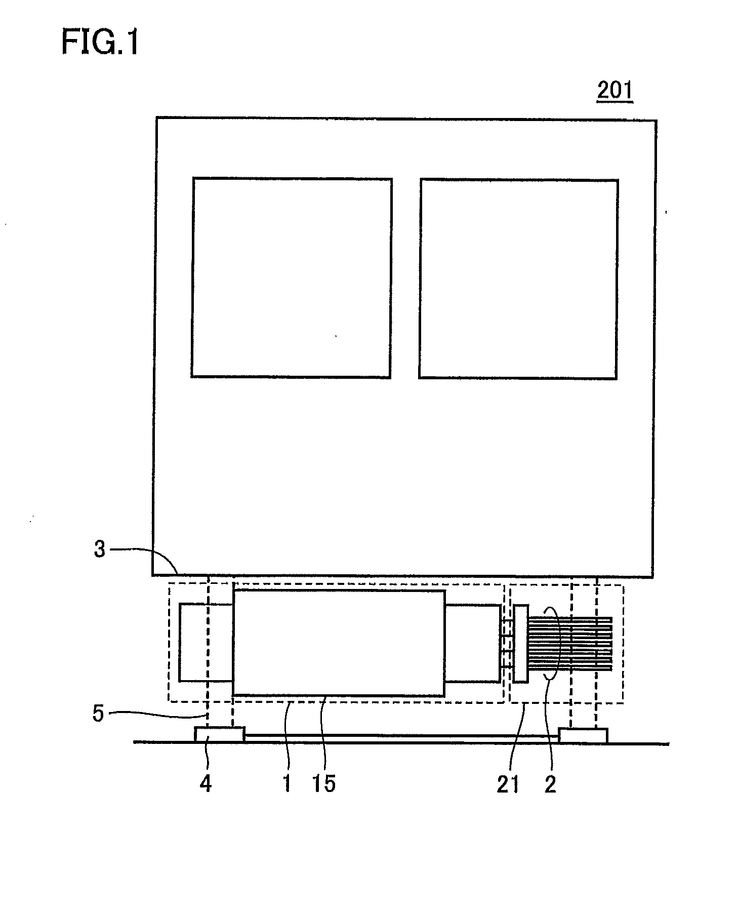
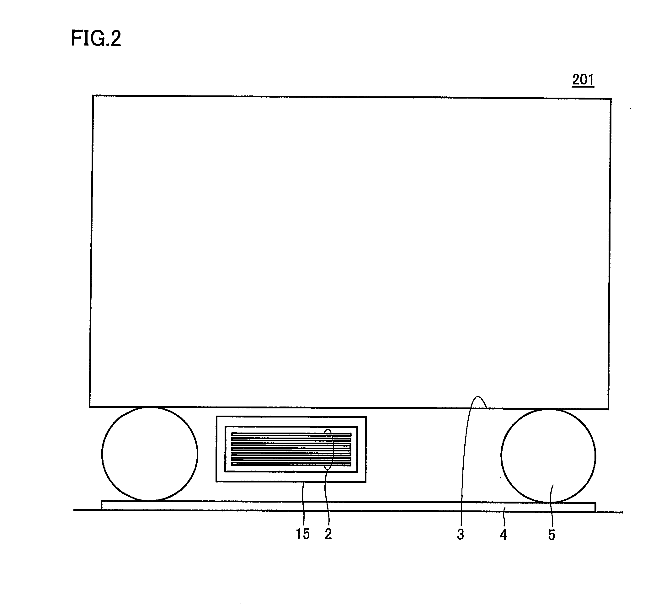
[0040]FIG. 1 is a front view of a vehicle according to a first embodiment of the present invention. FIG. 2 is a side view of the vehicle according to the first embodiment of the present invention. FIG. 3 is a top view of the vehicle according to the first embodiment of the present invention.
[0041]Referring to FIGS. 1 to 3, a vehicle 201 is, for example, a train that runs on a rail 4, and includes a transformer 101 and a wheel 5. Transformer 101 includes a transforming unit 1 and a cooling unit 21. Transforming unit 1 includes a tank 15. In FIG. 3, an arrow A represents a traveling direction of vehicle 201.
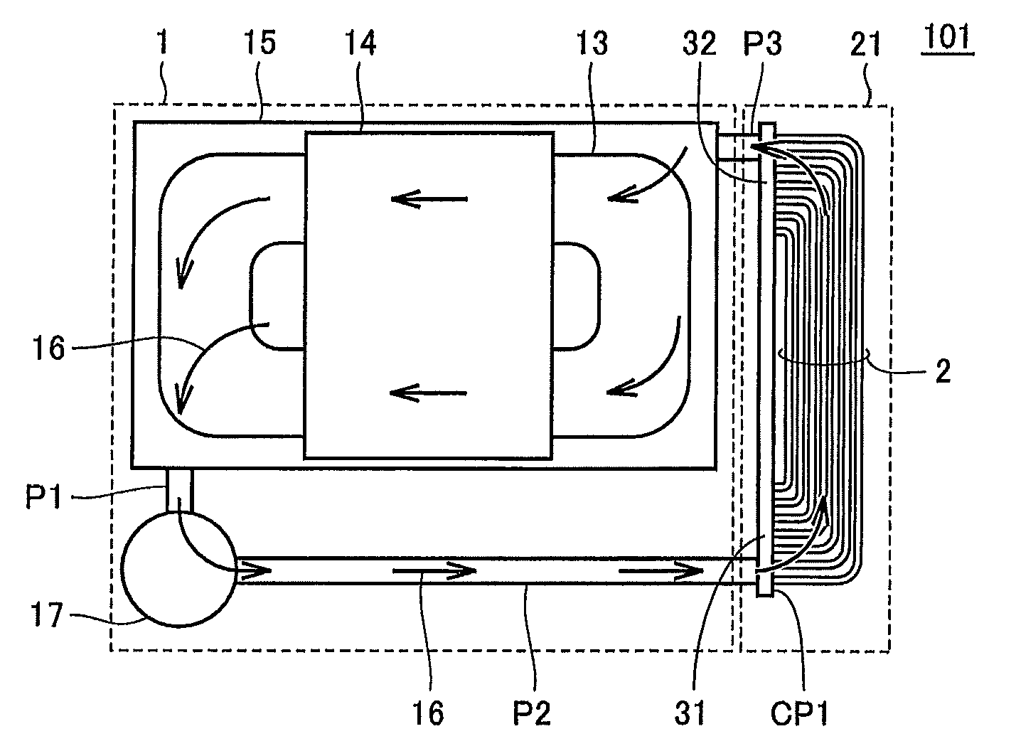
[0042]Transforming unit 1 is present near a side surface of cooling unit 21 in transformer 101, and a floor 3 of the vehicle is present near an upper surface of cooling unit 21. Tank 15 is attached under floor 3 of vehicle 201. Cooling unit 21 also includes a plurality of cooling pipes 2 that are arranged in seven stages horizontally to the ground, and are arranged in seven stages ...
second embodiment
[0073]The present embodiment relates to a transformer in which the arrangement of cooling pipes is modified, as compared to the transformer according to the first embodiment. The transformer according to the present embodiment is the same as the transformer according to the first embodiment except for the contents described below.
[0074]FIG. 12 is a diagram showing in detail the configuration of a cooling unit in the transformer according to the second embodiment of the present invention. FIG. 12 corresponds to a top view of the vehicle shown in FIG. 3, wherein an arrow A represents the traveling direction of the vehicle. For the sake of simplicity, common pipe CP1 and pipes P2, P3 are not shown.
[0075]FIG. 13 is a diagram showing the cooling unit viewed in a direction XIII in FIG. 12. FIG. 14 is a diagram showing the cooling unit viewed in a direction XIV in FIG. 12.
[0076]Referring to FIGS. 12 to 14, the transformer according to the second embodiment of the present invention includes...
third embodiment
[0084]The present embodiment relates to a transformer in which the cross-sectional shape of cooling pipes is modified, as compared to the transformer according to the first embodiment. The transformer according to the present embodiment is the same as the transformer according to the first embodiment except for the contents described below.
[0085]FIG. 15 is a diagram showing in detail the configuration of a cooling unit in a transformer according to a third embodiment of the present invention. FIG. 15 corresponds to a top view of the vehicle shown in FIG. 3, wherein an arrow A represents the traveling direction of the vehicle. For the sake of simplicity, common pipe CP1 and pipes P2, P3 are not shown.
[0086]FIG. 16 is a diagram showing the cooling unit viewed in a direction XVI in FIG. 15. FIG. 17 is a diagram showing the cooling unit viewed in a direction XVII in FIG. 15.
[0087]Referring to FIGS. 15 to 17, the transformer according to the third embodiment of the present invention incl...
PUM
 Abstract
Description
Claims
Application Information
 - R&D Engineer
- R&D Manager
- IP Professional
- Industry Leading Data Capabilities
- Powerful AI technology
- Patent DNA Extraction
Browse by: Latest US Patents, China's latest patents, Technical Efficacy Thesaurus, Application Domain, Technology Topic, Popular Technical Reports.
© 2024 PatSnap. All rights reserved.Legal|Privacy policy|Modern Slavery Act Transparency Statement|Sitemap|About US| Contact US: help@patsnap.com