Headlight optical axis adjustment device

a technology of optical axis and adjustment device, which is applied in the direction of lighting support device, transportation and packaging, lighting and heating apparatus, etc., can solve the problems of inability to adjust the pitch angle of the vehicle finely, inhibit durability, and confuse the drivers of oncoming vehicles, etc., to achieve unnecessary adjustment and enhance durability.

Inactive Publication Date: 2012-01-19
ORMON CORP
View PDF1 Cites 1 Cited by
  • Summary
  • Abstract
  • Description
  • Claims
  • Application Information

AI Technical Summary

Benefits of technology

[0017]In a first and second conventional arts, however, unnecessary operations of an actuator still exist, and a further improvement is desired in terms of further enhancing durability.
[0018]In other words, in the first conventional art, a tilt adjustment of an optical axis of a headlight based on a pitch angle of a vehicle is performed once while the vehicle is stopped and the tilt adjustment is performed for every predetermined interval while the vehicle remains stopped, but at least one tilt adjustment and the tilt adjustment of every interval are performed even in a stable state where the passenger does not go in / out and the baggage is not being loaded / unloaded, and thus the adjustments are waste, and improvement is desired in terms of further enhancing the durability.
[0019]In the second conventional art, the tilt adjustment of the optical axis is performed both while the vehicle is stopped and while it is traveling at a steady rate, but as there is no limitation (one adjustment and adjustment of every interval) as in the first conventional art while the vehicle is stopped, the actuator such as the motor operates every time the pitch angle changes, and unnecessary tilt adjustment is frequently performed even when the passenger goes in / out or when the baggage is being loaded / unloaded, and thus improvement is desired in terms of further enhancing the durability.
[0020]The present invention aims to provide a headlight optical axis adjustment device which avoids unnecessary adjustment by performing optical adjustment while the vehicle is stopped only in necessary situations, thereby further enhancing the durability.
[0028]According to the present invention, the optical axis adjustment of the headlight based on the pitch angle of the vehicle is permitted only when the opened / closed state of the open / close unit such as doors is in the “opened state”, where the opened state is when the passenger goes in / out or when the baggage is being loaded / unloaded to and from the vehicle, and thus the optical axis adjustment while the vehicle is stopped is performed only in necessary situations and unnecessary adjustment can be avoided, and further enhancement in the durability of the optical axis adjustment actuator (such as the motor) can be achieved.

Problems solved by technology

If a number of passengers or an amount of load of the vehicle are changed even if the cutoff line is appropriately set as above, the cutoff line moves to the upper side, which may dazzle the drivers of oncoming vehicles and the like.
However, the pitch angle of the vehicle finely fluctuates not only when the number of passengers or the amount of load are changed, but also when the passengers goes in / out or when the baggage is being loaded / unloaded to and from the vehicle, and also fluctuates when accelerating or decelerating during traveling or riding over bumps of the road surface.
Thus, an optical axis adjustment mechanism of the headlight operates every time the pitch angle changes if the device simply “tilts and adjusts the optical axis of the headlight in a direction of canceling the pitch angle of the vehicle”, and thus operation frequency of actuators such as a motor arranged in the mechanism increases thereby inhibiting durability.
In other words, in the first conventional art, a tilt adjustment of an optical axis of a headlight based on a pitch angle of a vehicle is performed once while the vehicle is stopped and the tilt adjustment is performed for every predetermined interval while the vehicle remains stopped, but at least one tilt adjustment and the tilt adjustment of every interval are performed even in a stable state where the passenger does not go in / out and the baggage is not being loaded / unloaded, and thus the adjustments are waste, and improvement is desired in terms of further enhancing the durability.

Method used


Image

  • Headlight optical axis adjustment device
  • Headlight optical axis adjustment device
  • Headlight optical axis adjustment device

Examples


first example

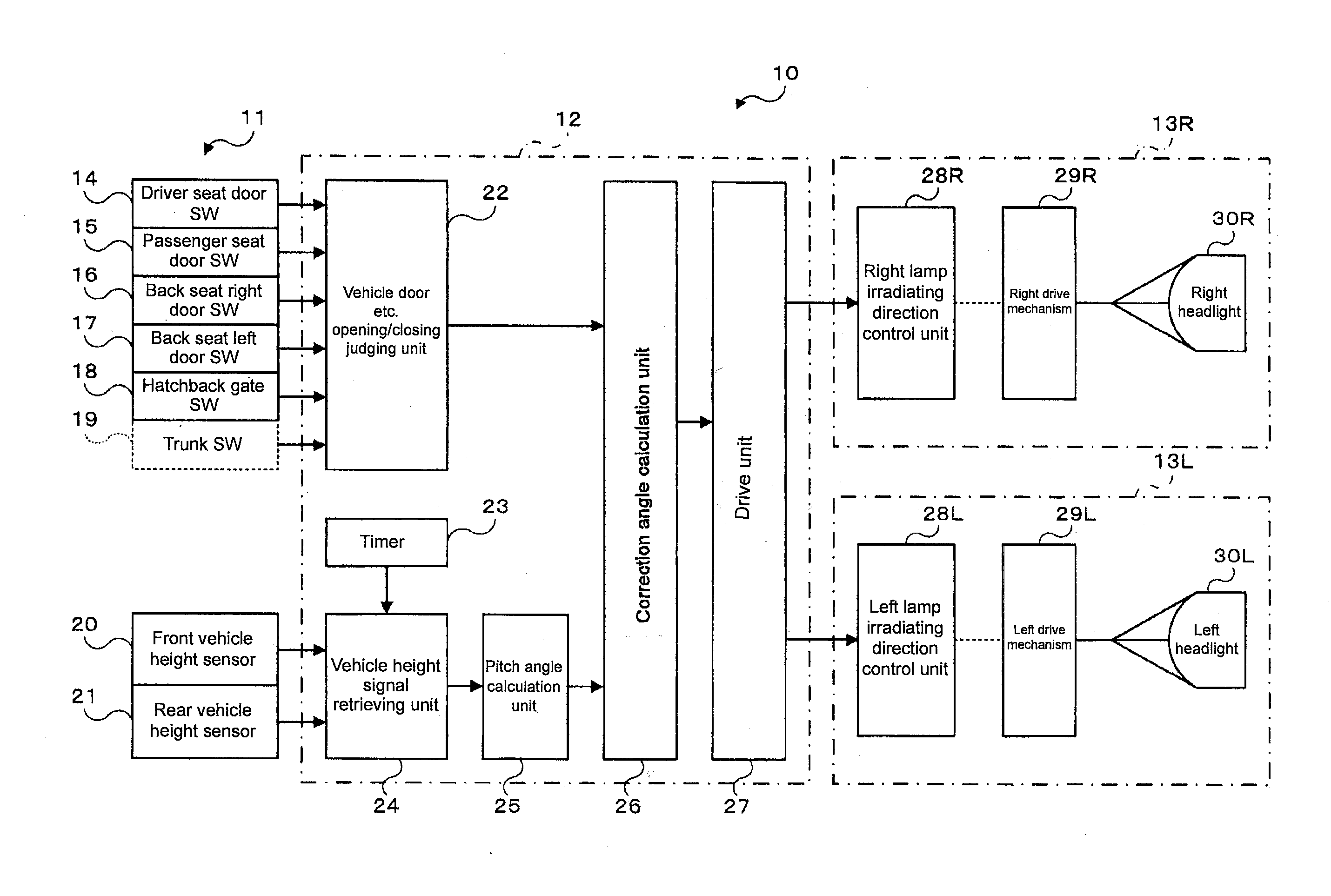
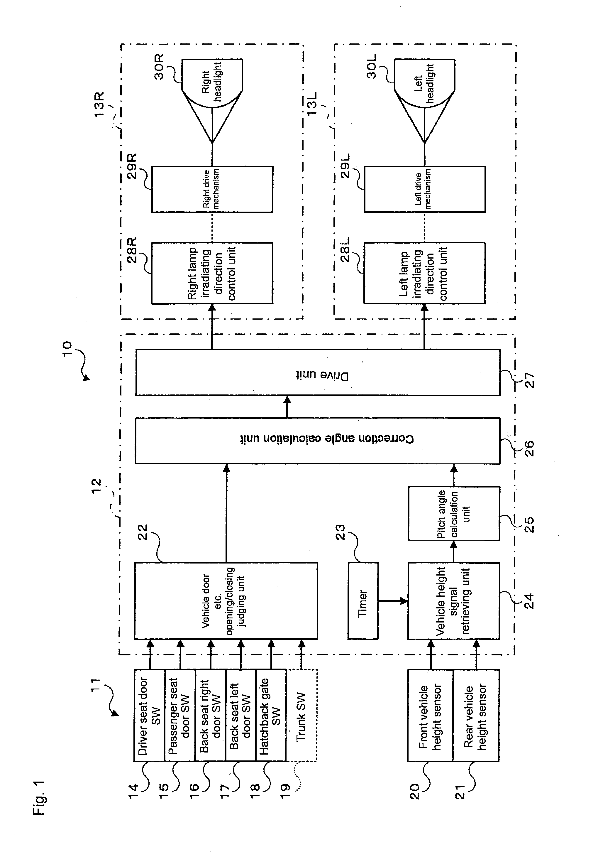
[0056]FIG. 4 shows a view of an operation flow in a first example. In this example, the opening / closing of the doors (driver seat door, passenger seat door, back seat right door, back seat left door, hatching gate, trunk) is judged by the vehicle door etc. opening / closing judging unit 22 (step S11), where when judged that one or more doors is opened (“YES” in step S11), presumption and judgment are made as being in a situation where the passenger goes in / out or the baggage is being loaded / unloaded, and the change in the pitch angle θ generated during the door opened state is calculated from the detection signals (Hf, Hr) of the front vehicle height sensor 20 and the rear vehicle height sensor 21, and the control amount of each drive mechanism (right drive mechanism 29R and left drive mechanism 29L) of the right lamp ASSY 13R and the left lamp ASSY 13L is determined based on the calculation result, so that the optical axes of the right headlight 30R and the left headlight 30L are adj...

second example

[0059]FIG. 5 shows a view of an operation flow in a second example. In this example, the opening / closing of the door (driver seat door, passenger seat door, back seat right door, back seat left door, hatchback gate, trunk) is judged by the vehicle door etc. opening / closing judging unit 22 (step S21), where when judged that one or more doors are opened (“YES” in step S21), presumption and judgment are made as being in a situation where the passenger goes in / out or the baggage is being loaded / unloaded, and the optical axes of the right headlight 30R and the left headlight 30L are adjusted to “lower side” (preferably lowermost side) (step S22).

[0060]Herein, adjusting the optical axis to “lower side” means the following. Each drive mechanism (right drive mechanism 29R and left drive mechanism 29L) of the right lamp ASSY 13R and the left lamp ASSY 13L moves the optical axis (accurately, tilt angle of reflector) of the right headlight 30R and the left headlight 30L, but the movement amoun...

third example

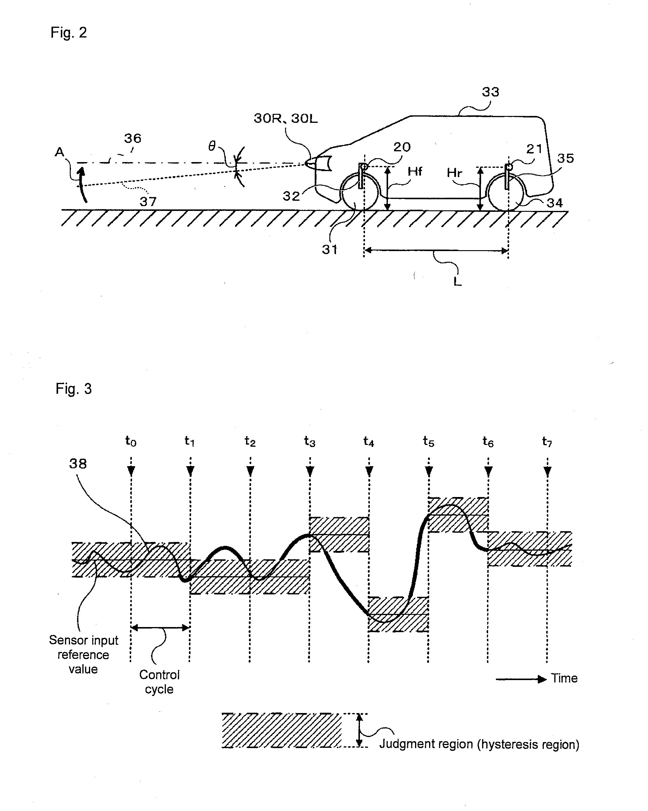
[0062]FIG. 6 shows a view of an operation flow in a third example. In this example, the opening / closing of the doors (driver seat door, passenger seat door, back seat right door, back seat left door, hatching gate, trunk) is judged by the vehicle door etc. opening / closing judging unit 22 (step S31), where when judged that one or more doors are opened (“YES” in step S31), presumption and judgment are made as being in a situation where the passenger goes in / out or the baggage is being loaded / unloaded, and only the lower side control of the optical axis of the headlight is permitted (step S33) only when both or one of the detection signals (Hf, Hr) of the front vehicle height sensor 20 and the rear vehicle height sensor 21 exceeds the judgment region (hysteresis region: Hopen herein) of predetermined upper and lower widths (step S32), and the optical axes of the right headlight 30R and the left headlight 30L are adjusted (step S34).

[0063]In step S33, the reason for “permitting only the...


PUM


Abstract

The present invention aims to perform optical axis adjustment while a vehicle is stopped only in necessary situations and to avoid unnecessary adjustment, and to further enhance durability. A headlight optical axis adjustment device for adjusting an optical axis of a headlight based on a pitch angle of the vehicle includes an opened / closed state detection section for detecting an open / closed state of an open / close unit where the opened state is when a passenger gets on / out or when a baggage is being loaded / unloaded to and from the vehicle; and an optical axis adjustment permitting section for permitting optical axis adjustment of the headlight based on the pitch angle of the vehicle when the opened state of the open / close unit is detected by the opened / closed state detection section.

Description

PRIOR APPLICATIONS[0001]This application is a divisional of and claims the benefit of co-pending U.S. patent application Ser. No. 12 / 241,315, filed on Sep. 30, 2008, titled “Headlight Optical Axis Adjustment Device”, and is incorporated herein by reference.BACKGROUND OF THE INVENTION[0002]1. Technical Field[0003]The present invention relates to a headlight optical axis adjustment device also referred to as “auto levelizer” used in vehicles such as an automobile.[0004]2. Related Art[0005]According to provision of safety standard (Department of Transportation Law No. 67, Jul. 28, 1951) of Road Trucking Vehicle Law, vehicles such as automobiles (hereinafter referred to as a vehicle) must be provided with a “running headlight” (so-called high beam) and a “passing headlight” (so-called low beam), or a “light distribution variable headlight” which is a combination of the above (combination of high beam and low beam).[0006]The “running headlight” is provided to check obstructions in terms ...

Claims


Application Information

Patent Timeline
Patent Type & Authority Applications(United States)
IPC IPC(8): B60Q1/04
CPCB60Q1/10B60Q2300/14B60Q2300/132B60Q2300/116
Inventor TODANI, AKINOBUORIGANE, TOSHINORI
Owner ORMON CORP
Why Eureka
Try Eureka