System and method for measuring x-ray beam profile using an area detector

a technology of a detector and a beam profile, applied in the field of system and method for measuring x-ray beam profile using an area detector, can solve the problems of affecting the quality of a generated image, affecting the accuracy of a given image, and all detectors also have gain variations, so as to achieve a simple and relatively quick process of beam calibration

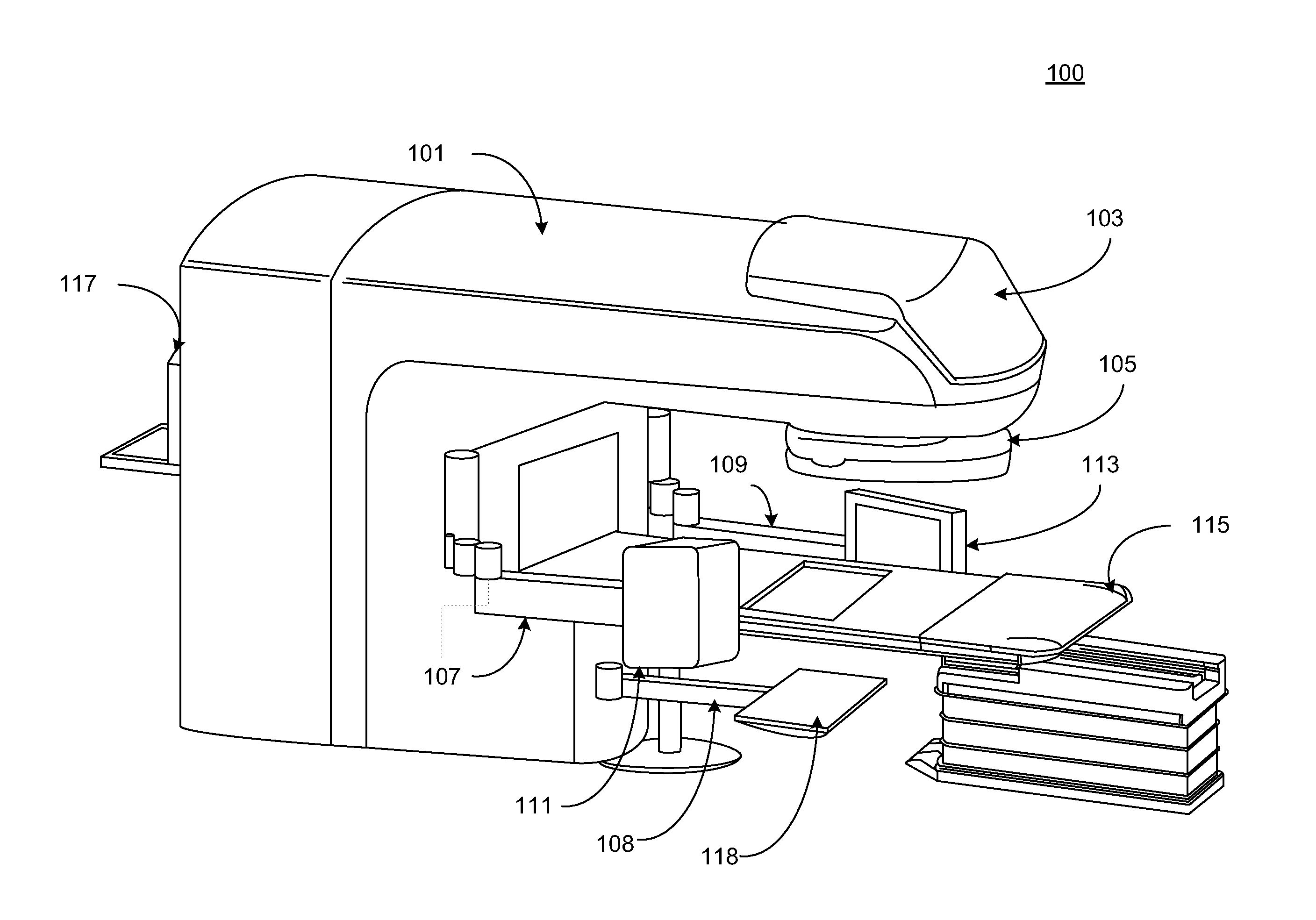
Active Publication Date: 2012-01-19
VARIAN MEDICAL SYST INT AG +1
View PDF2 Cites 20 Cited by
  • Summary
  • Abstract
  • Description
  • Claims
  • Application Information

AI Technical Summary

Benefits of technology

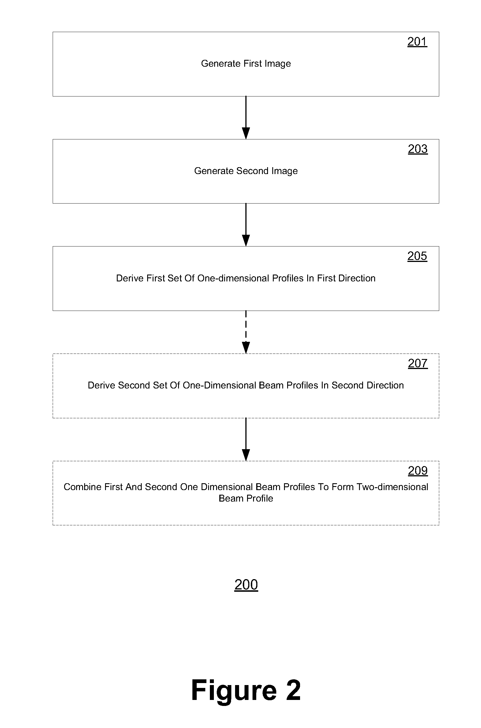
[0008]The claimed subject matter describes a novel technique to measure the beam profile using an area detector. No special requirement is needed for the detector and without requiring prior calibration. In one embodiment, the technique comprises generating two images from an area detector, deriving one or more sets of one-dimensional beam profile measurements from the generated images, and decoupling measured gain effects and flux intensity measurements from the sets of one-dimensional beam profiles, thereby advantageously providing a simple and relatively quick process to perform beam calibration. The technique provides a method of generating a beam profile for the x-ray field and a gain profile for the detector, which can used to properly calibrate the detector such as if the field were flat.

Problems solved by technology

Unfortunately, the generation of non-uniform beam fields is common in many radiology and medical imaging devices.
This non-uniformity, when not properly calibrated for, can cause unintended artifacts in generated images which may significantly impact the quality of a generated image.
In practice however, practically all detectors also have gain variations caused by inherent imperfections in the sensors and the associated electronic circuitry.
Unfortunately, conventional gain calibration techniques also remove flux intensity variations.
However, this approach suffers from several significant drawbacks: the scanning mechanism is cumbersome and the measurement time required is often lengthy since many beam pulses are required.
Moreover, geometric pointing inaccuracies and global flux intensity variations from scan-to-scan can limit the accuracy of the final result.
While more time-efficient than using a single point of a detector, the inherent non-uniformity among one or more pixels of the x-ray detector can detrimentally affect the accuracy of a beam profile thus measured.

Method used


Image

  • System and method for measuring x-ray beam profile using an area detector
  • System and method for measuring x-ray beam profile using an area detector
  • System and method for measuring x-ray beam profile using an area detector

Examples


Embodiment Construction

[0022]Reference will now be made in detail to several embodiments. While the subject matter will be described in conjunction with the alternative embodiments, it will be understood that they are not intended to limit the claimed subject matter to these embodiments. On the contrary, the claimed subject matter is intended to cover alternative, modifications, and equivalents, which may be included within the spirit and scope of the claimed subject matter as defined by the appended claims.

[0023]Furthermore, in the following detailed description, numerous specific details are set forth in order to provide a thorough understanding of the claimed subject matter. However, it will be recognized by one skilled in the art that embodiments may be practiced without these specific details or with equivalents thereof. In other instances, well-known methods, procedures, and components, have not been described in detail as not to unnecessarily obscure aspects and features of the subject matter.

[0024...


PUM


Abstract

The claimed subject matter describes a novel technique to measure the beam profile using an area detector. In one embodiment, a set of one-dimensional beam profile measurements is performed by taking two images under the same source conditions but at two different positions of the detector, with each position of the detector shifted by a certain distance in the direction corresponding to the direction of the one-dimensional profile measurement. In further embodiments, a set of two-dimensional beam profile measurements is achieved by determining a second set of one-dimensional profiles from the same sampling points in a second direction and building a two-dimensional map of the beam profile by correlating the first one-dimensional profile measurement with the second one-dimensional profile measurement.

Description

CLAIM OF PRIORITY[0001]This application claims priority to the provisional application entitled, “System and Method for Measuring X-Ray Beam Profile Using Area Detector,” filed Jul. 16, 2010, application No. 61 / 365,204.TECHNICAL BACKGROUND[0002]The usage of area x-ray beams is common in the field of x-ray imaging and external radiation treatment to generate images of a target volume. For many imaging applications, a beam of x-rays or other radiation particles is directed from a radiation source and through a target volume or object. The traversing particles of the beam are collected in an imager or detector positioned on the far side of the target volume with respect to the source, and the data acquired by the acquisition (reception) of the particles in the imager may be subsequently used to generate an image of the target volume.[0003]Certain characteristics of the particular beam used in acquiring the images are also critical to many applications, and may have a significant impact...

Claims


Application Information

Patent Timeline
Patent Type & Authority Applications(United States)
IPC IPC(8): G06K9/36
CPCA61B6/4266A61B6/582A61N5/1075A61B2017/00725A61B6/5205A61B2019/524A61N2005/1061A61B2090/3762
Inventor SUN, MINGSHANSTAR-LACK, JOSHVIRSHUP, GARYMORF, DANIELTHIEME-MARTI, STEFAN JOCHEM
Owner VARIAN MEDICAL SYST INT AG
Why Eureka
Try Eureka