
Dental restoration system and method thereof

Inactive Publication Date: 2012-01-19
ZUGA MEDICAL
View PDF13 Cites 5 Cited by
  • Summary
  • Abstract
  • Description
  • Claims
  • Application Information

AI Technical Summary

Benefits of technology

[0012]In various embodiments, the dental restoration system may further comprise a means of measuring the shape of the crown base part that is not surrounded by the shape determiner. It may further comprises a means of determining the shape of the entire crown base based on the shape determiner and the measure

Problems solved by technology

As known to a skilled doctor or dentist, it is difficult to make clean margin for the reasons that the gum bleeds after prep; the soft tissue pushes back and occupies the space between the gum and prepped tooth; the abutment shoulder is lower than the gum level and buried inside in the gum tissue.
However, this time-consuming and labor-intensive procedure still can't guarantee a clear margin for the crown, because the gum will push back and resume more or less to its original condition, after the retraction cord is removed.
For a traditional implant crown, the retraction cord cannot be packed between the gum and implant, because the operation would separate the gum attached to the implant, and destroy the connection between the periodontal tissue and implant, which may cause the bone recession later.
If serious, the operation may lead to the failure of the implantation.
Disadvantageously, the procedure is complicated and needs to use a lot of small accessories.
This procedure eliminates the doctor's role in making the implant crown directly by working in the patient's mouth, reduces the accuracy of the operation, increases the lab fee and accessory expenses, burdens the patient with more office visits, and demands a lot more steps for the doctor to bring back the abutment to the right position.
However, the procedure of Korwin involves the management of a big number of the adjustable elements, and is still complicated, expensive, and labor intensive for a dentist.
The CAD / CAM can't be used to make a crown on implant, because (i) currently there is no direct abutment set up in the patient's mouth; (ii) the direct modification of an implant abutment is currently not available; and (iii) the part of the abutment which is covered by the gum cannot be detected by the CAM / CAD sensor.

Method used


Image

  • Dental restoration system and method thereof
  • Dental restoration system and method thereof
  • Dental restoration system and method thereof

Examples


Embodiment Construction

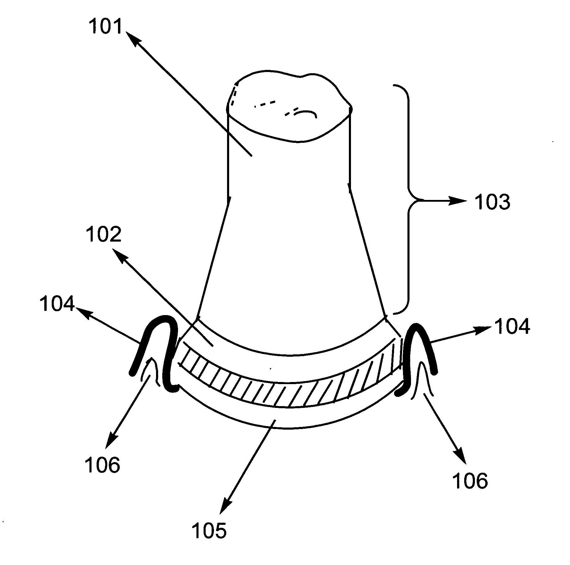
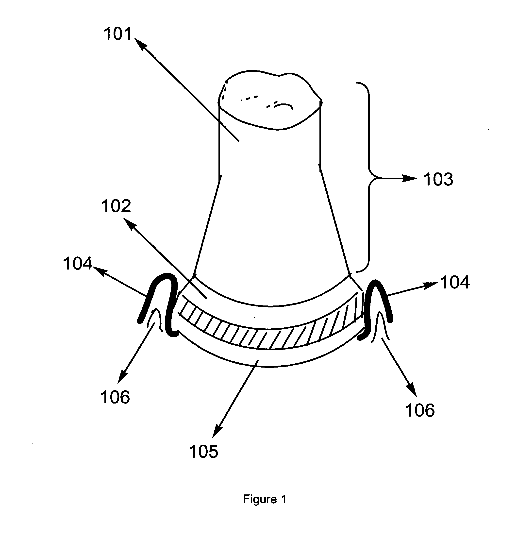
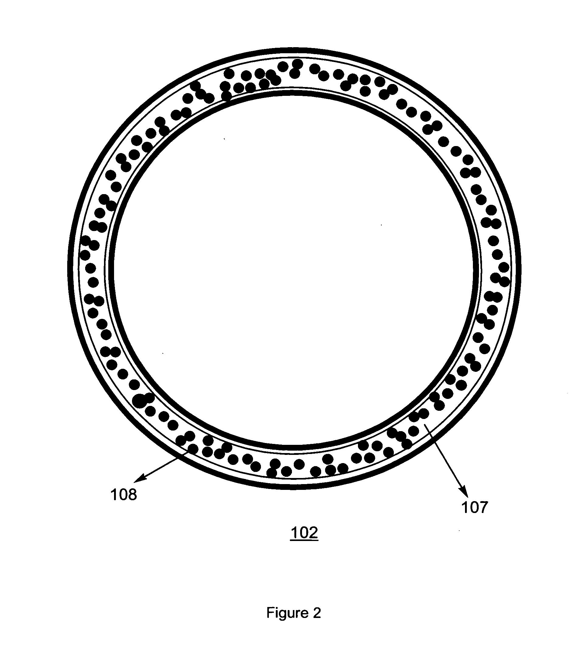
[0022]With reference to FIG. 1, the dental restoration system comprises a crown base 101 and a shape determiner 102. In preferred embodiments, the shape determiner of the invention may be a single piece with homogenous texture made of any suitable material such as metal, alloy, polymer, and composite material. The shape determiner 102 may be a regular or irregular ring directly surrounding the apical (bottom) part of the crown base 101. It may also be a regular or irregular C-shaped structure incompletely surrounding the crown base 101. In the interface between 101 and 102, the determiner 102 conforms to, or intimately contacts with, the shape (surface contour) of the bottom part of the crown base as surrounded by 102. In other words, the internal shape of the determiner 102 carries the accurate information of the internal shape of the corresponding portion of the crown to be made. Preferably, the external shape of the determiner 102 may also determine a corresponding portion of the...


PUM


Abstract

The invention provides a dental restoration system comprising a crown base such as a dentin or an abutment and a shape determiner that surrounds and measures the shape of an apical part in the crown base. The invention also provides a method of dental restoration, which comprises measuring the shape of the crown base that is not surrounded by the shape determiner; determining the shape of the entire crown base; and preparing a crown to be secured on the crown base. The invention exhibits merits such as a much simpler procedure, less gum injury and bone recession, cost-effectiveness, and excellent compatibility with CAD / CAM system, among others.

Description

BACKGROUND OF THE INVENTION[0001]This application claims priority based on the U.S. Provisional application 61 / 162,333 filed on Mar. 22, 2009, which is incorporated herein by reference in its entirety.[0002]The present invention relates to a dental restoration system and method thereof. It finds particular application in conjunction with dental prostheses such as crown, and will be described with particular reference thereto. However, it is to be appreciated that the present invention is also amenable to other dental prostheses such as veneers and bridges.[0003]For a tooth that is damaged or lost, a dentist will design a crown to be secured on the remaining dentin or on an implant, and restore the function of that tooth. In designing a dental crown, it is critically important that the crown can accurately fit the oral environment, particularly, to fit the spatial configuration of the gum area around the tooth, for the purpose of, in addition to an aesthetic appearance, the hygiene i...

Claims


Application Information

Patent Timeline
IPC IPC(8): A61C13/01A61C5/08A61C5/77
CPCA61C5/08A61C13/0003A61C5/10A61C5/70A61C5/77
Inventor WANG, CHAN Q.
Owner ZUGA MEDICAL
Learn More