Wireless transceiver apparatus having circuit unit forming frequency resonance mode when operated under reception mode

Active Publication Date: 2012-01-19
REALTEK SEMICON CORP
View PDF6 Cites 2 Cited by
  • Summary
  • Abstract
  • Description
  • Claims
  • Application Information

AI Technical Summary

Benefits of technology

[0006]Therefore, in order to solve the problem mentioned above, one of the objectives of the present invention is to provide a wireless transceiver apparatus that shares an antenna module, wherein the antenna module is not directly connected to a circuit at a transmitter end or a circuit at a receiver end via a switch component, and a wireless communication signal (e.g., a transmission signal or a reception signal) does not directly pass through the switch component. Therefore, such design is helpful to mitigating the signal loss and improving the signal isolation and power handling capability.

Problems solved by technology

However, since the transmission signal / reception signal will pass through the switch component 101A / 101B, the parasitic effects resulted from the complementary metal-oxide-semiconductor (CMOS) process will still let the signal bear a certain loss even if the other working mode (e.g. a transmission mode) is disabled.
As a result, the gain and linearity of the signal would be affected.
However, the significant effect of this conventional method is the greatly increased chip area.
Thus, this method is only applicable to a circuit that transmits and receives narrowband signals.
Since the power handling capability requires accurate control, an extra model for describing the power has to be developed, which increases the design time inevitably.

Method used


Image

  • Wireless transceiver apparatus having circuit unit forming frequency resonance mode when operated under reception mode
  • Wireless transceiver apparatus having circuit unit forming frequency resonance mode when operated under reception mode
  • Wireless transceiver apparatus having circuit unit forming frequency resonance mode when operated under reception mode

Examples


Embodiment Construction

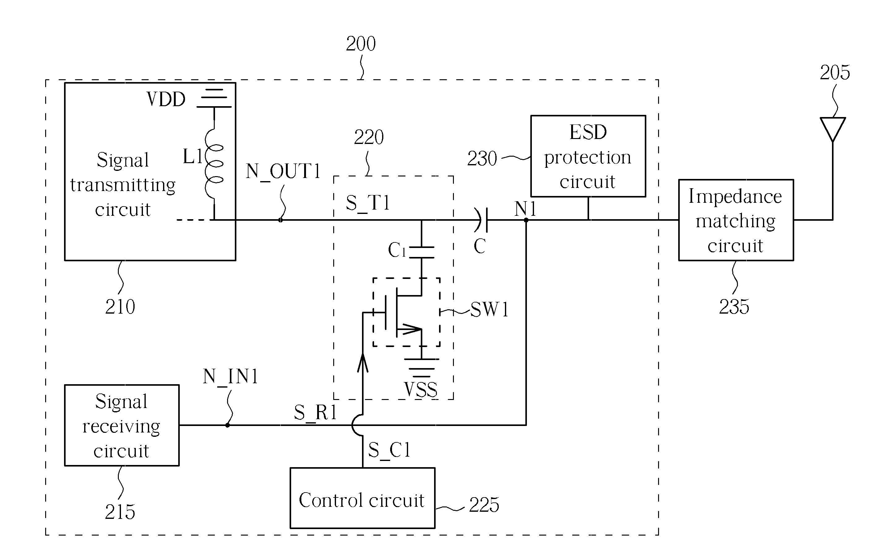
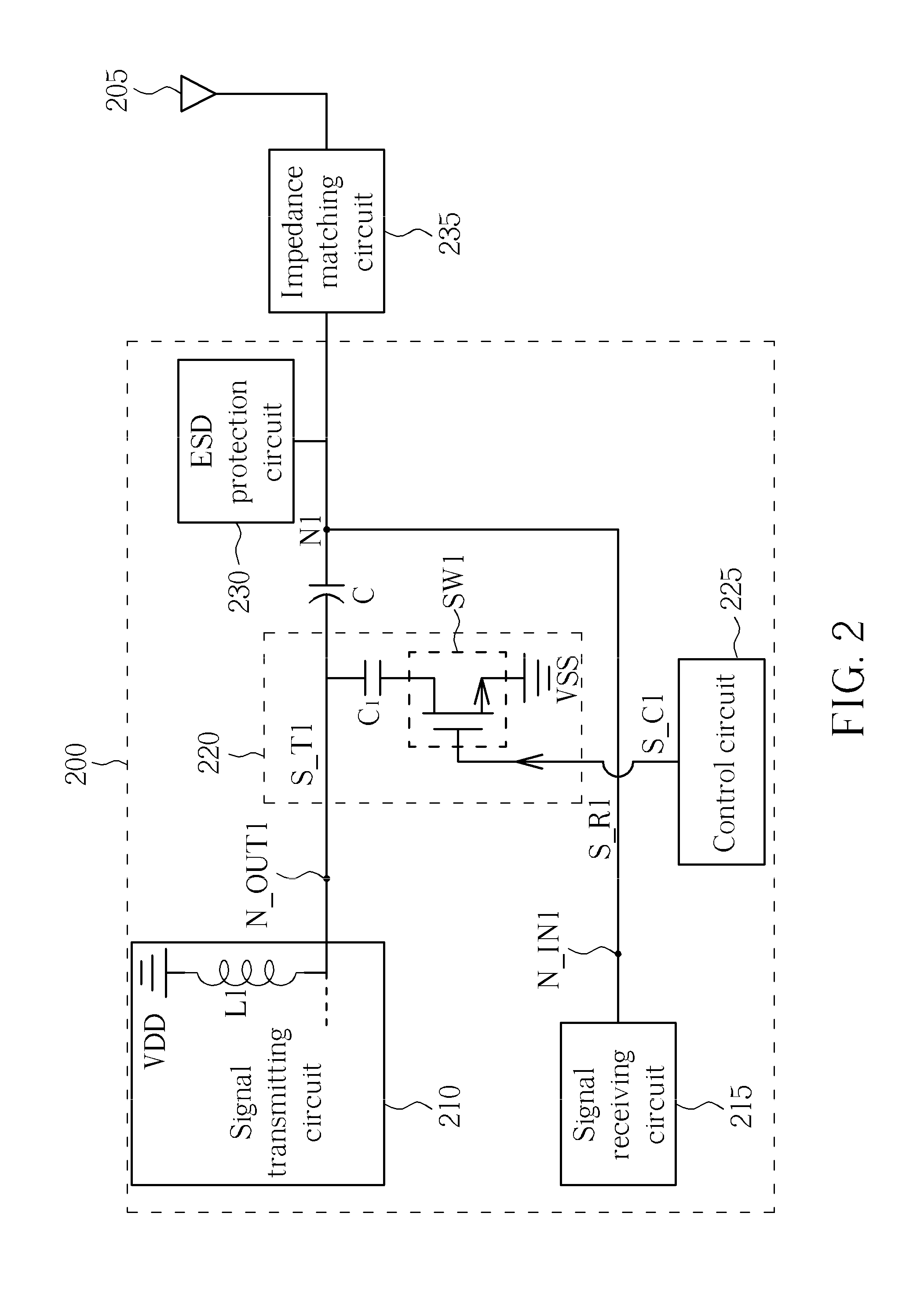
[0013]Please refer to FIG. 2, which is a diagram illustrating a wireless transceiver apparatus 200 according to a first exemplary embodiment of the present invention. The wireless transceiver apparatus 200 is electrically connected to an antenna module 205 via an impedance matching circuit 235. The wireless transceiver apparatus 200 includes a node N1, a signal transmitting circuit 210 (e.g., a circuit including a power amplifier), a signal receiving circuit 215 (e.g., a circuit including a low-noise amplifier), a circuit unit 220, a control circuit 225 and an electrostatic discharge (ESD) protection circuit 230. The signal transmitting circuit 210 includes an output port N_OUT1 utilized for outputting a transmission signal S_T1 in the transmission mode. The circuit unit 220 is coupled to the output port N_OUT1 of the signal transmitting circuit 210. The signal receiving circuit 215 includes a receiving port N_IN1 utilized for receiving a wireless communication signal S_R1 in the re...


PUM


Abstract

A wireless transceiver apparatus is provided. The wireless transceiver apparatus includes a signal transmitting circuit, a circuit unit, and a signal receiving circuit. The signal transmitting circuit includes a first output port and is utilized for outputting a first transmission signal via the first output port in a transmission mode. The circuit unit is coupled to the first output port of the signal transmitting circuit. The signal receiving circuit includes a first receiving port and is utilized for receiving a first wireless communication signal via the first receiving port in a reception mode. The first output port is coupled to the first receiving port at a first node. The circuit unit forms a frequency resonance mode to increase an impedance value of the signal transmitting circuit seen by a signal at the first node.

Description

BACKGROUND OF THE INVENTION[0001]1. Field of the Invention[0002]The present invention relates to a wireless transmitting and receiving mechanism, and more particularly, to a wireless transceiver apparatus that shares an antenna module.[0003]2. Description of the Prior Art[0004]In a wireless communication system, a design of a transmitting / receiving switch (T / R switch) is mainly based on signal insertion loss during signal transmitting, signal isolation between a transmission signal and a reception signal and power handling capability. In practice, no matter whether the T / R switch is realized utilizing a ready-made product or other manner, the cost and the circuit board complexity should be taken into consideration. Therefore, in recent years, with the development of semiconductor process and the requirement of the cost, more and more products aim at having a power amplifier and a T / R switch integrated into one chip simultaneously. Regarding most of the designs having the T / R switch ...

Claims


Application Information

Patent Timeline
IPC IPC(8): H04B1/44
CPCH04B1/48
Inventor LIN, YI-CHIEHCHEN, YU-HSIN
Owner REALTEK SEMICON CORP
Why Eureka
Try Eureka