Cpr chest compression machine stopping to detect patient recovery

a chest compression machine and chest compression technology, applied in the field of chest compression machines, can solve the problems of deteriorating compression quality, fatigued rescuers, and sometimes ineffective cpr for preventing damage to patients

Active Publication Date: 2012-01-19
PHYSIO CONTROL INC
View PDF3 Cites 70 Cited by
  • Summary
  • Abstract
  • Description
  • Claims
  • Application Information

AI Technical Summary

Benefits of technology

[0018]An advantage over the prior art is that patient recovery can be detected during automatic series of successive chest compressions and the compressions can be paused or ended so that the patient is not put at risk for feeling pain or discomfort from the chest compressions.

Problems solved by technology

A problem is that CPR is sometimes ineffective for preventing damage to the patient.
The most frequent example of such ineffectiveness is compressions that are not deep enough, or not frequent enough.
Even the best trained rescuers can become fatigued after delivering CPR, with the compressions deteriorating in quality.
Reaching the appropriate depth is difficult.
If the depth exceeds the range, the patient's ribs may break.
And, even for experienced rescuers, it is sometimes hard to discern the appropriate depth.
Reaching the appropriate depth is even more difficult if the patient is on a flexible mattress that partly recedes, as the rescuer is pushing from the top.
And CPR compressions are even more challenging, if the rescuer has to deliver them in a moving ambulance.
Although CPR chest compression machines can be used in conjunction with external defibrillators, not all ailments for which a CPR chest compression machine is used require defibrillation.
Although it is generally good to perform CPR chest compressions, it is sometimes difficult to know when to stop compressions.
This may cause the patient pain and discomfort, as well as potentially scaring them and causing additional emotional or physical trauma.
Even when the CPR chest compression machine helps the patient return to spontaneous circulation while they are still comatose, it is still desirable to stop the CPR chest compression machine promptly because 1) its compressions can interfere with the normal filling of heart chambers between spontaneous heart contractions, thus decreasing the cardiac output caused by those spontaneous heart contractions, and 2) its compressions can, under certain circumstances, increase the probability that the heart will return to ventricular fibrillation.

Method used


Image

  • Cpr chest compression machine stopping to detect patient recovery
  • Cpr chest compression machine stopping to detect patient recovery
  • Cpr chest compression machine stopping to detect patient recovery

Examples


Embodiment Construction

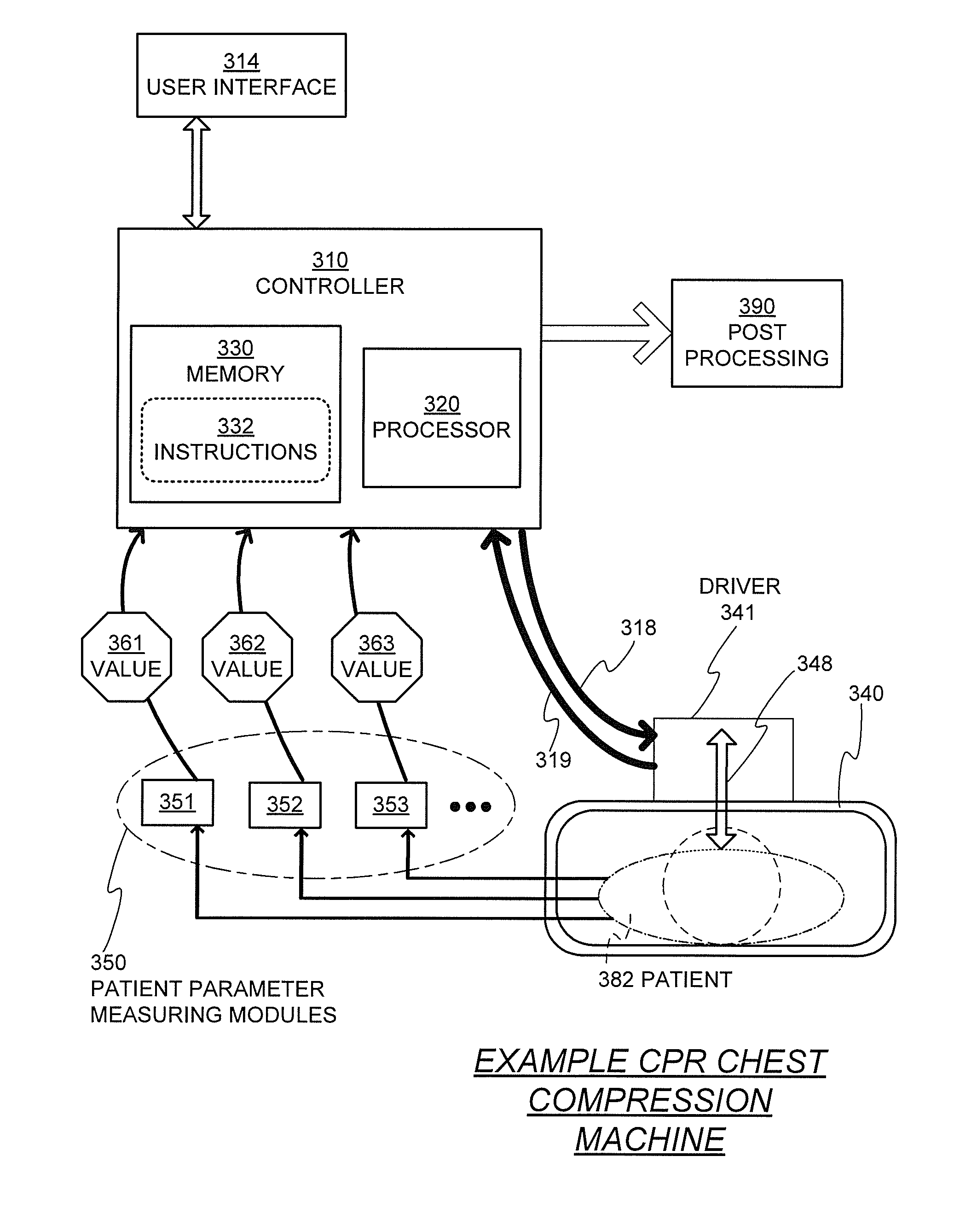
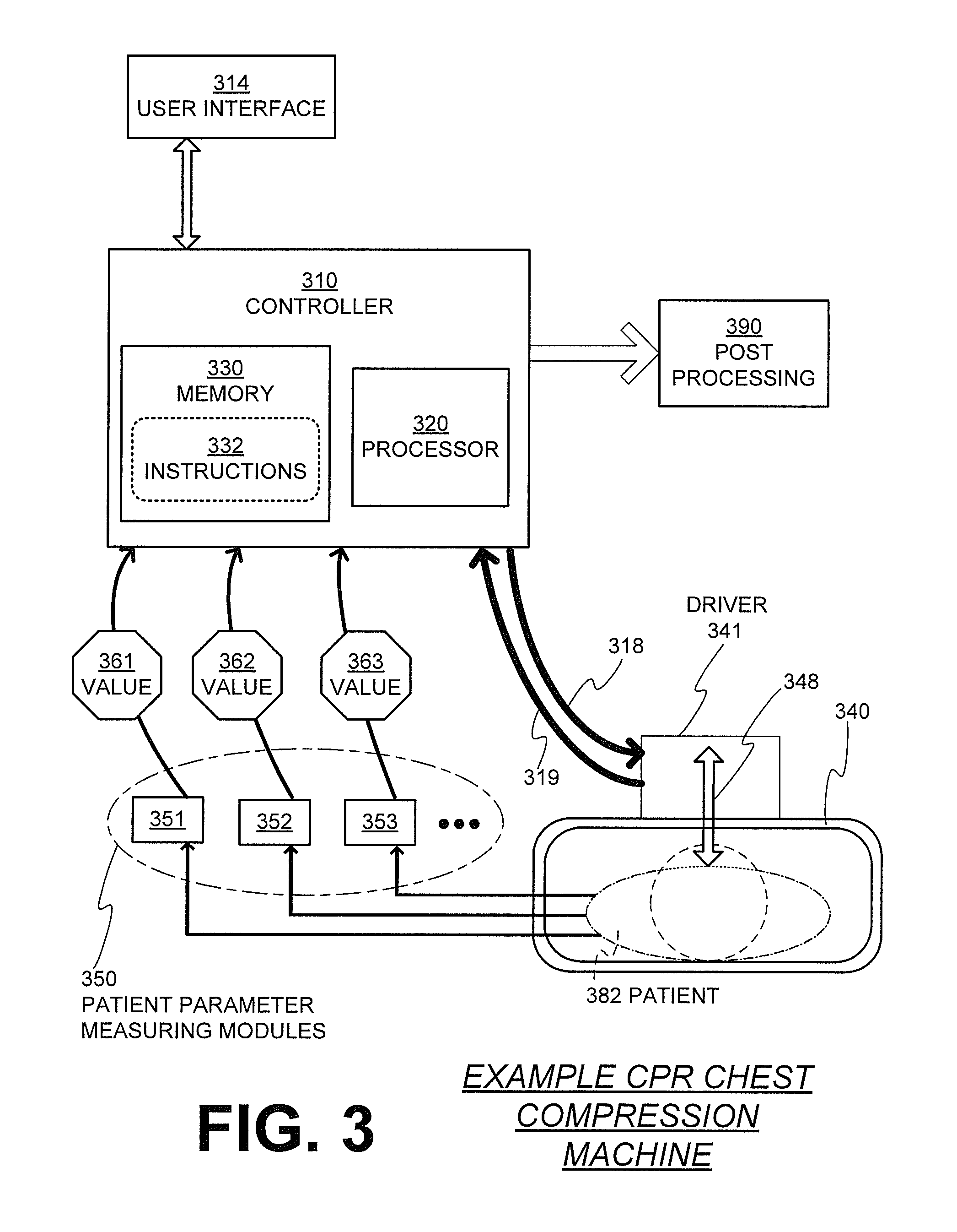
[0028]As has been mentioned, the present description is about medical devices, systems, and methods for stopping a CPR chest compression machine to detect patient recovery.

[0029]Embodiments are now described in more detail.

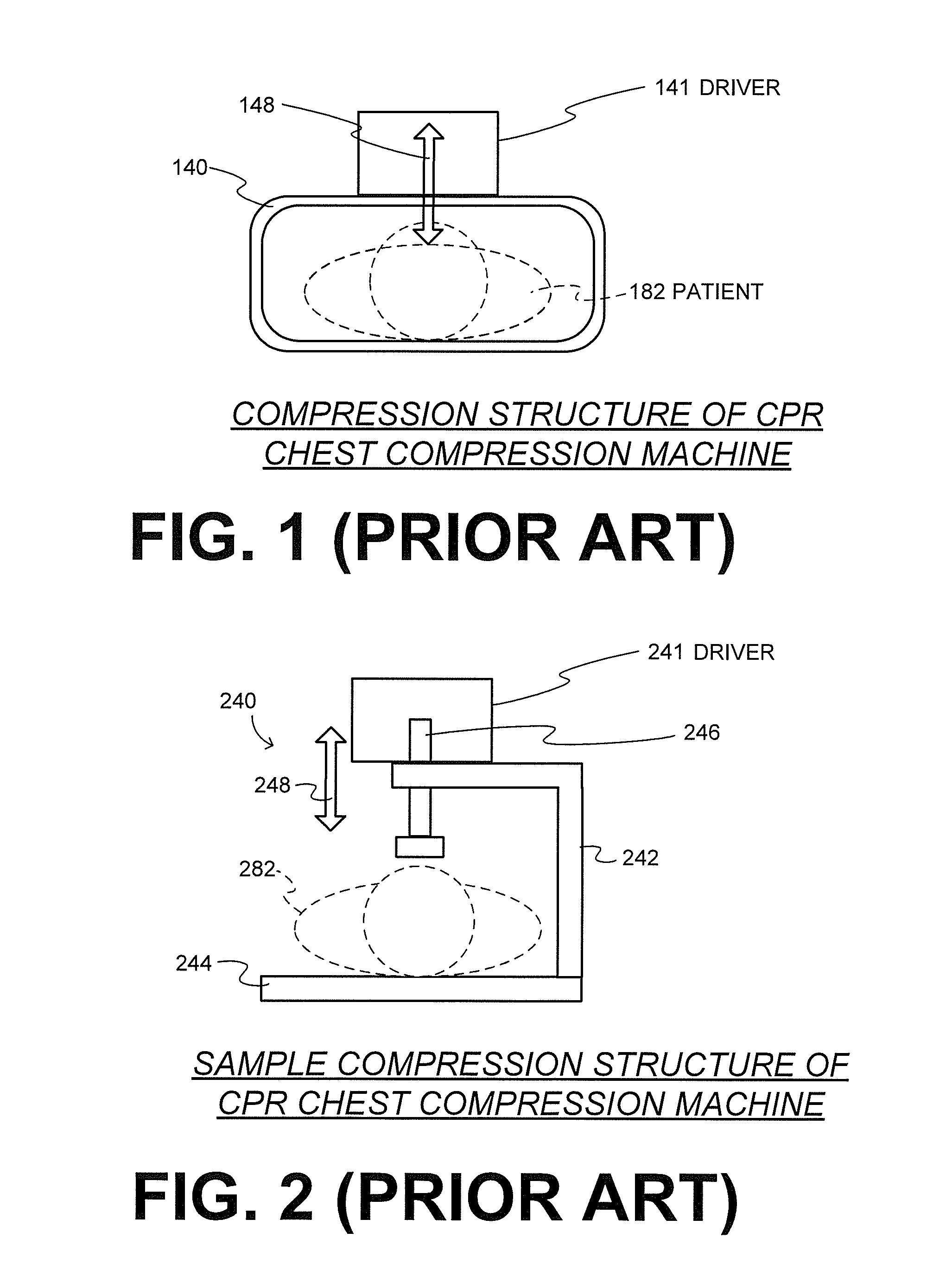
[0030]FIG. 1 is a diagram of an abstracted compression structure 140 of a CPR chest compression machine in the prior art. A patient 182 is placed within compression structure 140. A driver 141 is then controlled to drive the compression structure 140 to repeatedly compresses and releases their chest. These compressions and releases are designated by arrow 148, regardless of how effectuated.

[0031]Compression structure 140 is shown as reaching around the chest of patient 182. This alleviates the above-mentioned problem of the patient being on a flexible mattress, which causes ineffective CPR. Indeed, compressions 148 are with respect to compression structure 140, not the mattress. But structure 140 typically does not cover, for example, the head of patient 182.

[0032...


PUM


Abstract

Embodiments of the present concept are directed to CPR chest compression machines that include a sensor to detect a parameter about a patient, such as an indication of patient recovery, and include a processor that determines whether to cease series of successive compressions on the patient in response to the detected parameter.

Description

CROSS REFERENCE TO RELATED PATENT APPLICATIONS[0001]This patent application claims priority from the following Provisional Patent Applications: U.S.A. Provisional Patent Application Ser. No. 61 / 363,996, filed on Jul. 13, 2010; U.S.A. Provisional Patent Application Ser. No. 61 / 444,091, filed on Feb. 17, 2011; U.S.A. Provisional Patent Application Ser. No. 61 / 444,888, filed on Feb. 21, 2011; U.S.A. Provisional Patent Application Ser. No. 61 / 495,176, filed on Jun. 9, 2011. The disclosure of each provisional is hereby incorporated by reference for all purposes.FIELD[0002]This invention generally relates to CPR chest compression machines.BACKGROUND[0003]In certain types of medical emergencies, Cardio-Pulmonary Resuscitation (“CPR”) needs to be delivered to a patient. CPR includes repeatedly compressing the chest of the patient, to cause their blood to circulate some. CPR also includes delivering rescue breaths to the patient. A number of people are trained in CPR, just in case, even thou...

Claims


Application Information

Patent Timeline
Patent Type & Authority Applications(United States)
IPC IPC(8): A61H31/00
CPCA61H31/004A61H31/006A61H2201/1246A61H2230/305A61H2201/5097A61H2230/208A61H2201/5007A61B5/318A61B5/021A61B5/026A61B5/14542
Inventor BANVILLE, ISABELLE L.CHAPMAN, FRED W.SULLIVAN, JOSEPH L.DUKE, STEVEN
Owner PHYSIO CONTROL INC
Why Eureka
Try Eureka