Register access in distributed virtual bridge environment

Active Publication Date: 2012-01-19
IBM CORP
View PDF18 Cites 25 Cited by
  • Summary
  • Abstract
  • Description
  • Claims
  • Application Information

AI Technical Summary

Benefits of technology

[0010]At least one of the embodiments may facilitate efficient programming of registers in a highly integrated environment. The controlling bridge may provide trusted (e.g., known and secure) firmware used to control access considerations, such as security, routing, and availability in a consistent manner. The controlling bridge may be configured to access registers

Problems solved by technology

For example, contention for routing resources may exist when server computers are housed within racks for space and connectivity considerations, such as in a blade server computer arrangement.
The server computers may experience transmission bottlenecks and delays when forward

Method used


Image

  • Register access in distributed virtual bridge environment
  • Register access in distributed virtual bridge environment
  • Register access in distributed virtual bridge environment

Examples


Embodiment Construction

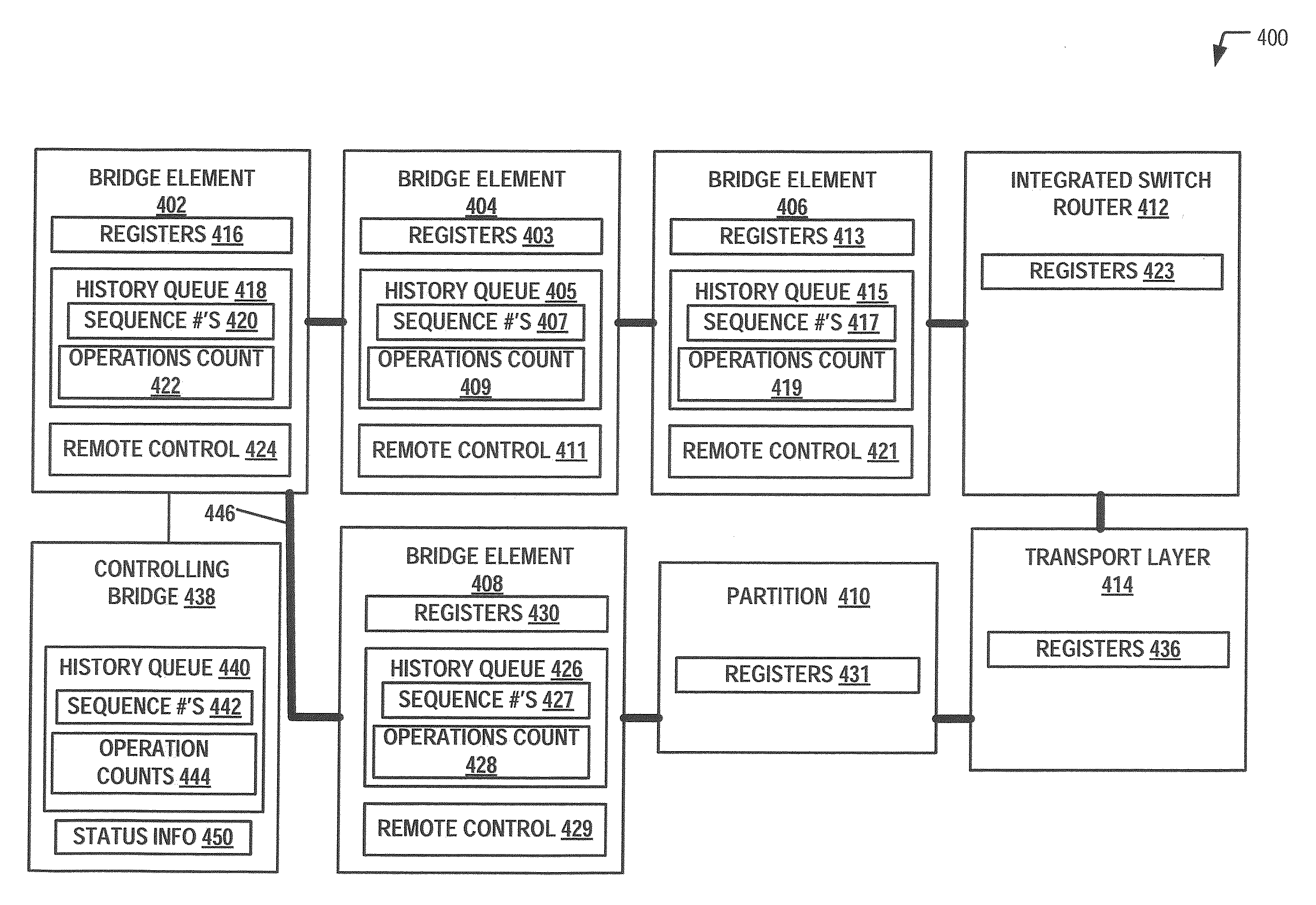
[0018]Firmware of a controlling bridge may control register load and store operations involving multiple, interconnected bridge elements. The controlling bridge may be directly coupled to a local bridge element via a Peripheral Component Interconnect Express (PCIe) and may communicate with the bridge elements using data frames that include register access requests. In a particular embodiment, the system may include a main register ring that uses a token protocol to access registers. An initiating bridge element making a register access request may wait for a token on the main register ring. The token may be used so that only the one bridge element having control of the token may access a target node at a time. When the token becomes available, the register access request may be placed on the main register ring for delivery to the target node. The register access address may be addressed to the bridge element or other target node. The target node may execute the register access reque...


PUM


Abstract

Systems and methods to perform a register access are described. A particular method includes receiving a data frame at a bridge element of a plurality of bridge elements in communication with a plurality of server computers. The data frame may include a register access request and may be forwarded from a controlling bridge in communication with the plurality of bridge elements. A register may be accessed and execution of the register access request may be initiated in response to receiving the data frame.

Description

I. FIELD OF THE DISCLOSURE[0001]The present disclosure relates generally to data communications, and more specifically, to accessing registers in a highly integrated computer network.II. BACKGROUND[0002]Server computers are continuously managed to enable access to shared switches and other traffic routing resources. For example, contention for routing resources may exist when server computers are housed within racks for space and connectivity considerations, such as in a blade server computer arrangement. The server computers may experience transmission bottlenecks and delays when forwarding data frames through centralized switches, such as shared top of rack switches.[0003]To illustrate, FIG. 1 shows a conventional blade server computer system 100. The system 100 includes a plurality of server computers 106-125 housed within racks 102, 104 and arranged into chassis 138, 140, 142, and 144. An illustrative server computer 106 may include a half-width information technology element (I...

Claims


Application Information

Patent Timeline
IPC IPC(8): G06F13/36H04L45/58
CPCH04L12/433H04L12/4641G06F15/1735H04L49/356H04L49/70H04L45/741H04L12/4645G06F13/36
Inventor CORRIGAN, MICHAEL J.ENGEBRETSEN, DAVID R.WALK, BRUCE M.
Owner IBM CORP
Why Eureka
Try Eureka