Power cord integrated hanger system for suspending a lighting fixture

a technology of power cords and lighting fixtures, which is applied in the direction of fixed installation, lighting and heating equipment, lighting support devices, etc., can solve the problems of power cords, relatively expensive and difficult installation, and rigid stem designs become impractical, and achieves high load bearing capacity, high degree of flexibility, and easy installation.

Active Publication Date: 2012-01-26
ABL IP HLDG
View PDF18 Cites 11 Cited by
  • Summary
  • Abstract
  • Description
  • Claims
  • Application Information

AI Technical Summary

Benefits of technology

[0006]The present invention provides a power cord integrated hanger system for suspending the power feed end of a lighting fixture below a ceiling structure. The hanger system of the invention completely hides the power cord while having a high load bearing capability. The invention further provides a hanger system having a high degree of flexibility, allowing the suspended lighting fixture to sway relatively freely during seismic events, up to + / −90 degrees from vertical. Hanger systems in accordance with the invention can be used to hang lighting fixtures below grid ceilings and other ceiling structures, and can be easily installed.
[0007]The power cord integrated hanger system of the invention includes a flexible load bearing inner suspension part and a flexible non-load bearing outer conductor part that acts as the “power cord” for the suspended lighting fixture. The inner suspension part is comprised of a strong flexible cable, such as aircraft cable, and bears the load of the lighting fixture. The flexible outer conductor part has an internal passageway, and electrical conductors running through it. An outer cover, which forms part of the outer conductor part, holds the electrical conductors in place and preferably conceals the conductors from view. The outer cover of the conductor part can be provided with different aesthetic qualities to enhance its visual appearance.
[0008]When installed, the non-load bearing conductor part surrounds the suspension cable so that the suspension cable is completely or substantially hidden from view. When installed, the outer conductor part of the hanger system becomes the visually dominant part of the system, and the hanger system will take on the external appearance of this visually dominant part. At the same time, the outer conductor part of the hanger system effectively manages the electrical conductors used to supply electrical power to the lighting fixture. It prevents tangles of wires that can occur where a plurality of electrical wires are used to wire the lighting fixture. The result is a hanger system for the feed end of a lighting fixture that presents a clean, finished look for a finished ceiling appearance.

Problems solved by technology

However, rigid stem designs became impractical with the introduction of earthquake building codes in earthquake-prone areas, such as California, which require that a fixture be allowed to sway during a seismic event.
However, ball stems are relatively costly and difficult to install.
The problem with aircraft cable is that the power cords for electrifying the lighting fixtures must be dropped next to the cable.
Power cords are visually objectionable and detract from the finished appearance of lighting installation.
However, ties, clips and cord managers fail to hide the power cord and themselves create visual detractions.
Cord managers can also inhibit the ability of the fixture to sway during seismic events.
The difficulty with this solution is that the connections between the attachment hardware and the flexible outer sheath create structural weak points along the length of the hanger, which compromise the hanger's load bearing capacity.
Also, while having a degree of flexibility, the metal sheath is not sufficiently flexible to allow the suspended fixture to experience a large degree of sway, with the sway generally being limited to a range of around + / −10 degrees from vertical.

Method used


Image

  • Power cord integrated hanger system for suspending a lighting fixture
  • Power cord integrated hanger system for suspending a lighting fixture
  • Power cord integrated hanger system for suspending a lighting fixture

Examples


Embodiment Construction

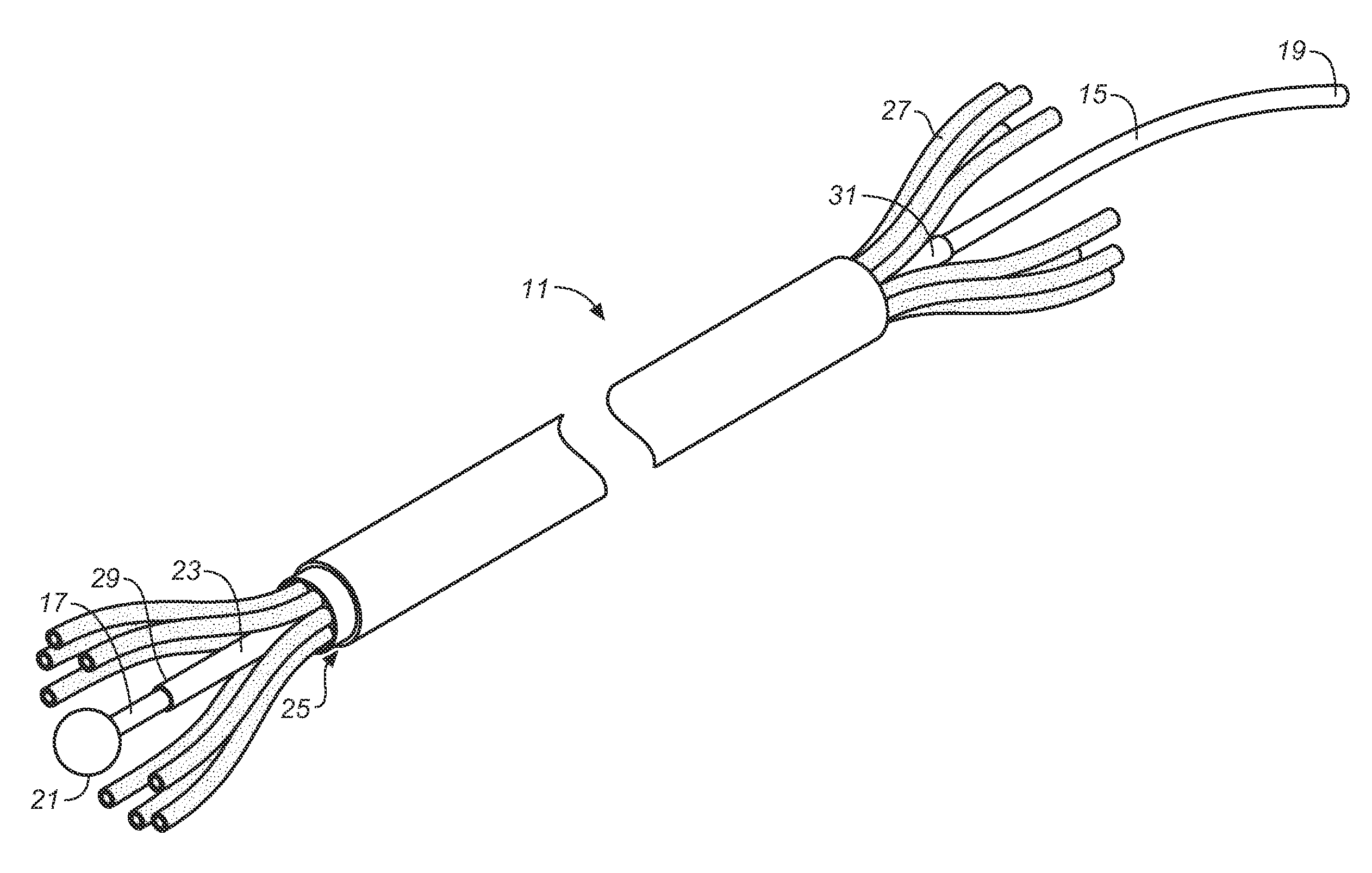
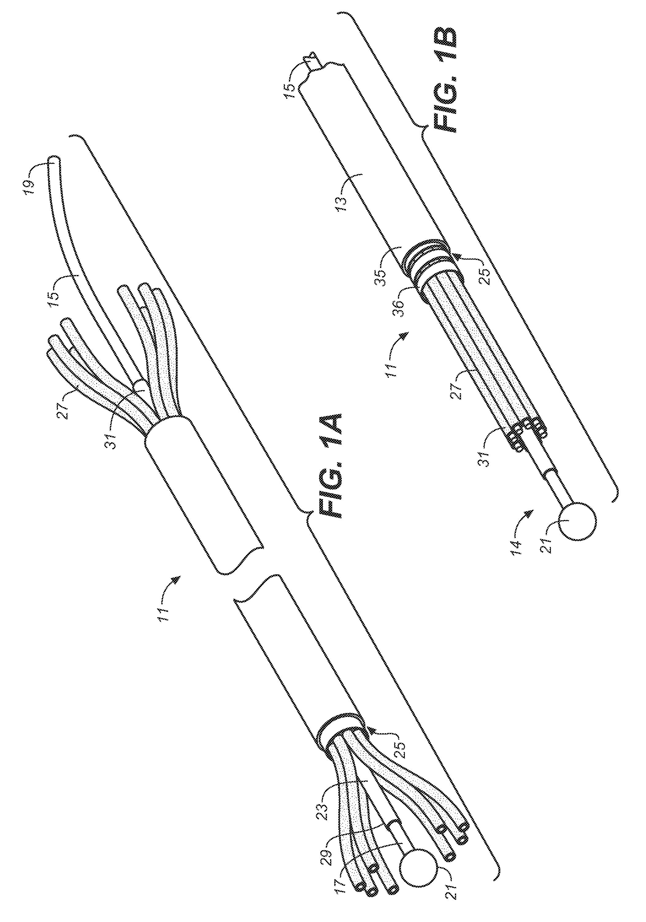
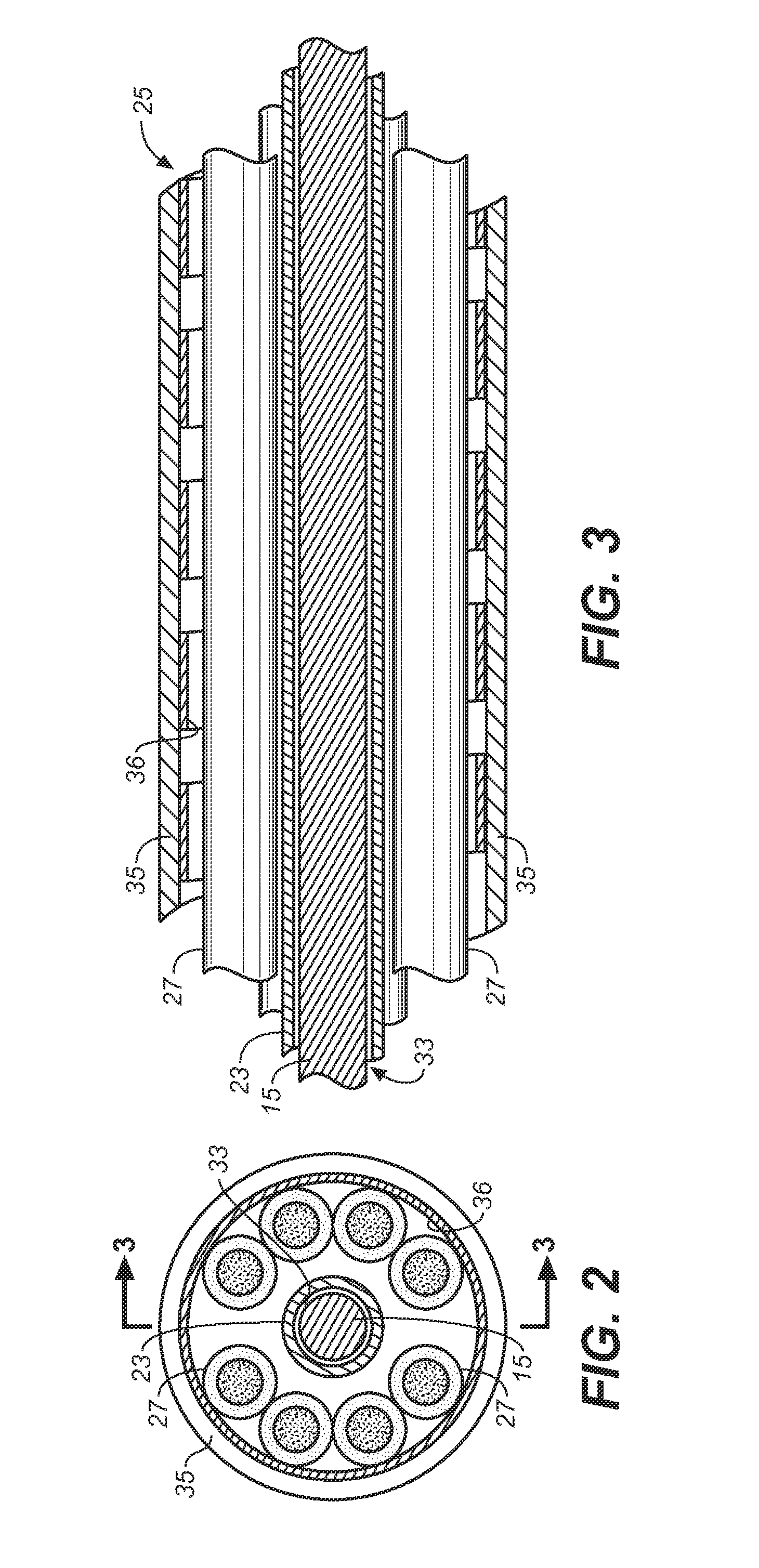
[0019]Referring now the drawings, FIGS. 1-3 illustrate an embodiment of a power cord integrated hanger system 11 in accordance with the invention, which is comprised of an elongated and flexible non-load bearing conductor part denoted by the numeral 13, and an elongated and flexible load bearing suspension part denoted by the numeral 14. The suspension part is comprised of a flexible suspension cable 15 having a bottom end 17, a top end 19, and a length exceeding the length of the conductor part. The length of the suspension cable is chosen in accordance with the desired suspension height of the lighting fixture.

[0020]The suspension cable 15 is preferably aircraft cable commonly used to suspend architectural lighting fixtures. Aircraft cable, which is made up of multiple strands of steel wire, has high tensile strength and is highly flexible. However, it is not intended that the flexible suspension part of the invention be limited to the use of aircraft cable. Other types of cable c...


PUM


Abstract

A power cord integrated hanger system for suspending a lighting fixture has a flexible load bearing inner suspension part and a flexible non-load bearing outer conductor part that acts as the “power cord” for the suspended lighting fixture. The flexible outer conductor part has an internal passageway for the inner suspension part. An outer cover of the outer conductor part holds electrical conductors in place in the outer conductor part and preferably conceals the conductors from view. The outer cover of the conductor part can be provided with different aesthetic qualities to enhance the visual appearance of the hanger system.

Description

BACKGROUND[0001]The present invention generally relates to the installation of electric lighting fixtures, and more particularly to the installation of ceiling suspended lighting fixtures having electrical power cords that must be extended between the fixtures and the overhead ceiling.[0002]Lighting designs for architectural spaces frequently include lighting fixtures suspended from an overhead ceiling structure where the lighting fixtures become an architectural element within the space. In office environments, a typical lighting installation will include the suspension of runs of direct or indirect, or direct / indirect, lighting fixtures below a ceiling such as a grid ceiling from multiple suspension points located on the ceiling. Each run of fixtures will require at least one power feed location where a potentially unsightly power cord must be run from the lighting fixture up to an electrical junction box above the ceiling. In older installations, the runs of lighting fixtures wer...

Claims


Application Information

Patent Timeline
Patent Type & Authority Applications(United States)
IPC IPC(8): H02G7/05
CPCF21S8/06H02G3/20F21V21/112F21V21/104H02G3/30
Inventor WU, XIAOPINGSHAHBAZ, MOHAMMAD ZAFAR
Owner ABL IP HLDG
Why Eureka
Try Eureka