Tilted bit rotary steerable drilling system

a drilling system and tilting bit technology, applied in the direction of directional drilling, earth drilling and mining, drilling machines and methods, etc., can solve the problem that the well profile of the borehole is relatively complex

Active Publication Date: 2012-01-26
BAKER HUGHES INC
View PDF3 Cites 96 Cited by
  • Summary
  • Abstract
  • Description
  • Claims
  • Application Information

AI Technical Summary

Benefits of technology

[0007]In aspects, the present disclosure provides an apparatus for forming a wellbore in a subterranean formation. The apparatus may include a shaft having an end portion, a drill

Problems solved by technology

Such boreholes can have rela

Method used


Image

  • Tilted bit rotary steerable drilling system
  • Tilted bit rotary steerable drilling system
  • Tilted bit rotary steerable drilling system

Examples


Embodiment Construction

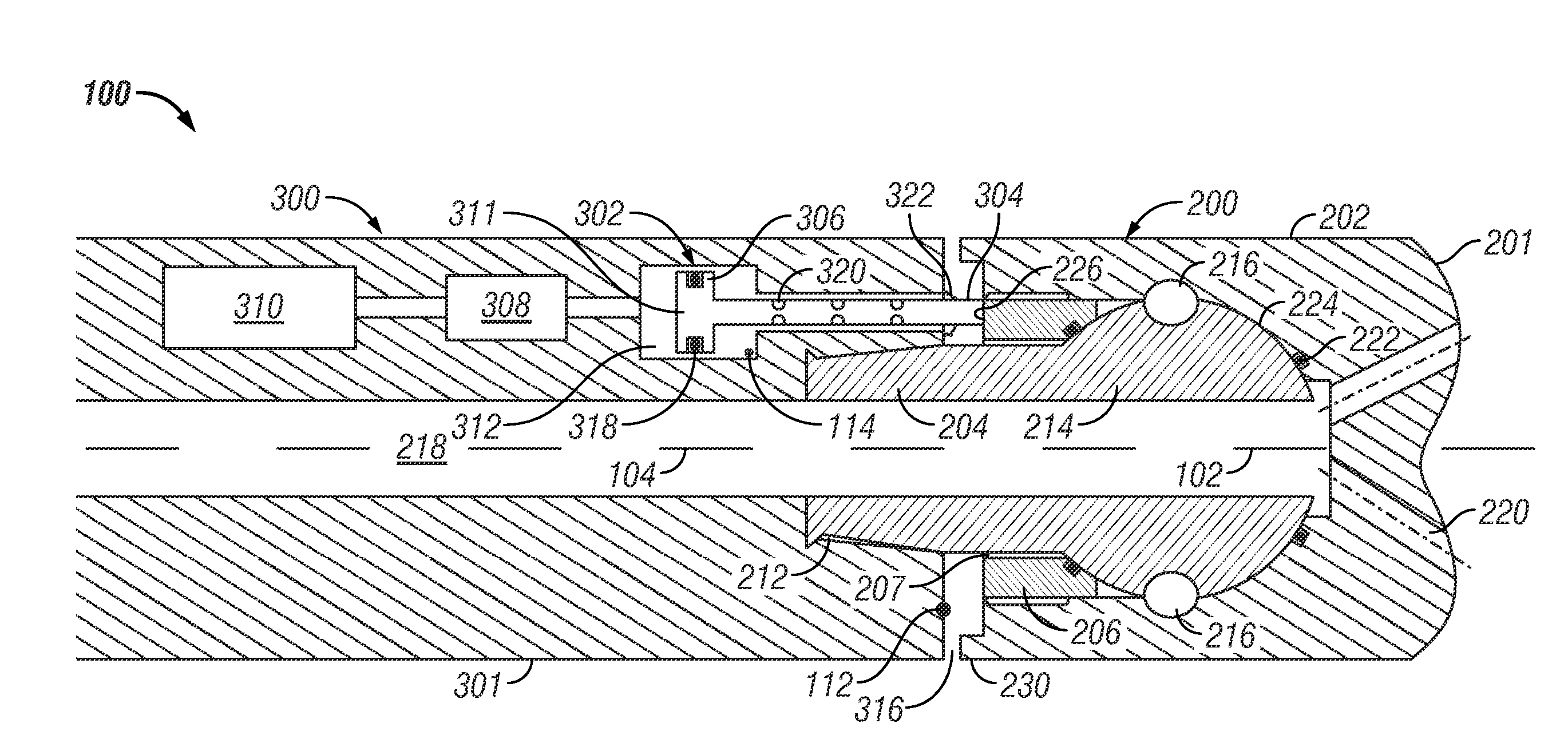
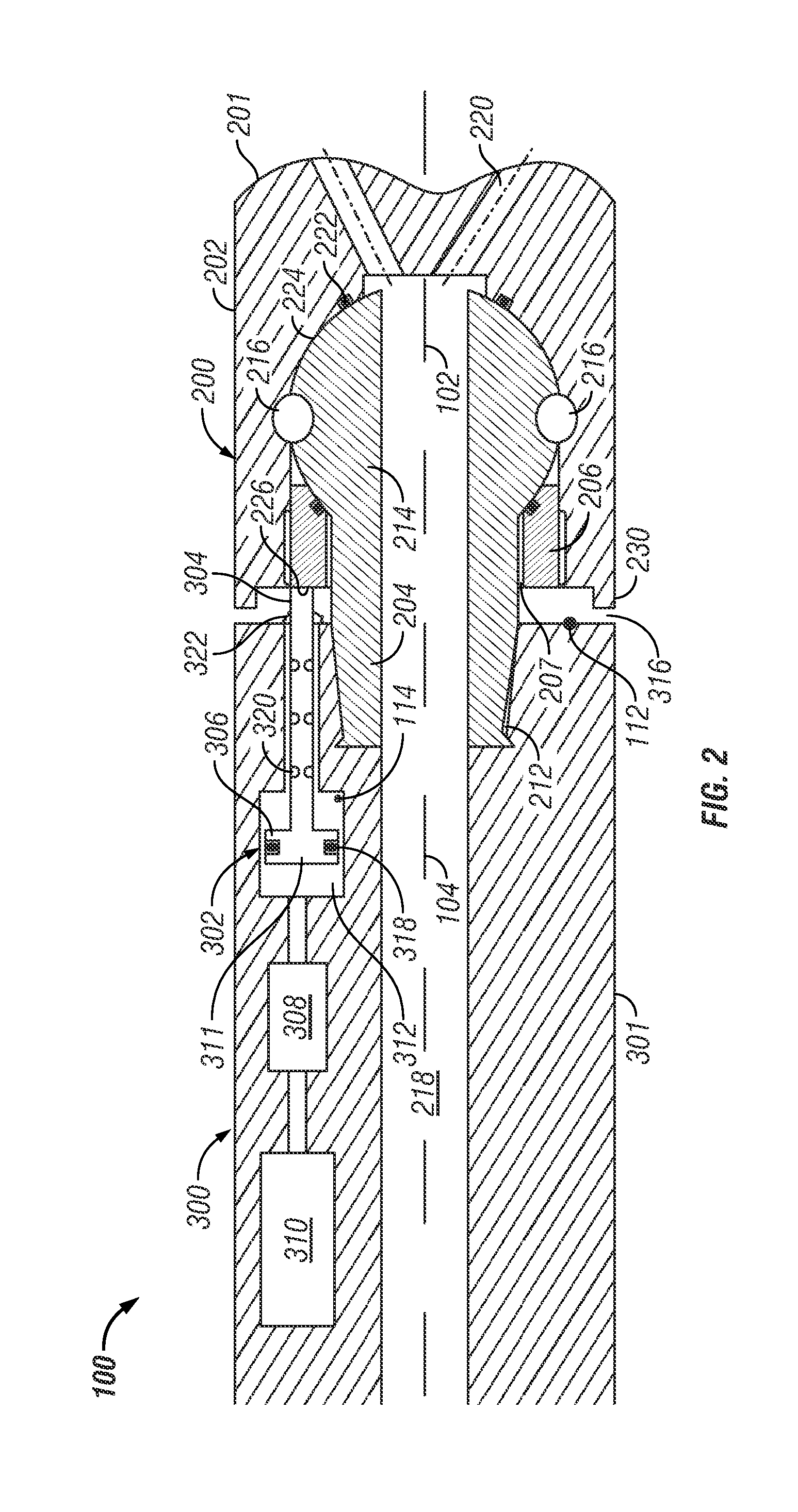
[0016]As will be appreciated from the discussion below, aspects of the present disclosure provide a rotary steerable system for drilling wellbores. In general, the described steering methodology may involve deflecting the angle of the drill bit axis relative to the tool axis by tilting a body of a drill bit. In some embodiments, the drill bit may be tilted by using an actuator assembly that applies a tilting force to the drill bit. To compensate for drill bit rotation, the force may be sequentially applied to a specified azimuthal or circumferential location on the drill bit in order to create a geostationary tilt; i.e., a tilt that consistently points the bit at a desired drilling direction even when the drill bit rotates. As will become apparent from the discussion below, rotary steerable systems in accordance with the present disclosure may be constructed such that the drill bit, which may include relatively high-wear components, may be readily disconnected from the actuator asse...


PUM


Abstract

A wellbore is formed by using an apparatus that may include a shaft having an end portion, a drill bit body tiltable about the end portion, and at least one actuator configured to apply a tilting force to the drill bit body.

Description

CROSS-REFERENCE TO RELATED APPLICATIONS[0001]This application claims priority from U.S. Provisional Application Serial No.: 61 / 366,453, filed Jul. 21, 2010, the disclosure of which is incorporated herein by reference in its entirety.BACKGROUND OF THE DISCLOSURE[0002]1. Field of the Disclosure[0003]This disclosure relates generally to oilfield downhole tools and more particularly to drilling assemblies utilized for directionally drilling wellbores.[0004]2. Background of the Art[0005]To obtain hydrocarbons such as oil and gas, boreholes or wellbores are drilled by rotating a drill bit attached to the bottom of a drilling assembly (also referred to herein as a “Bottom Hole Assembly” or (“BHA”). The drilling assembly is attached to the bottom of a tubing, which is usually either a jointed rigid pipe or a relatively flexible spoolable tubing commonly referred to in the art as “coiled tubing.” The string comprising the tubing and the drilling assembly is usually referred to as the “drill ...

Claims


Application Information

Patent Timeline
IPC IPC(8): E21B7/04
CPCE21B7/067E21B7/04
Inventor PETER, ANDREASWITTE, JOHANNESKOPPE, MICHAELTREVIRANUS, JOACHIM
Owner BAKER HUGHES INC
Why Eureka
Try Eureka