Frequency detection mechanism for a clock generation circuit

a clock generation circuit and frequency detection technology, applied in the field of frequency detection, can solve the problems of not being able to directly measure the output clock signal, ic pins may not be available for that purpose, and significantly slow production testing

Active Publication Date: 2012-01-26
APPLE INC
View PDF2 Cites 19 Cited by
  • Summary
  • Abstract
  • Description
  • Claims
  • Application Information

AI Technical Summary

Problems solved by technology

However, when the clock generation circuit is manufactured on an integrated circuit (IC), it may not be cost effective to directly measure the output clock signal during production testing of the IC for a variety of reasons.
More particularly, in some cases, IC pins may not be available for that purpose, unless special test mode interfaces are used.
This type of testing may significantly slow production testing.
Alternatively, it may be more costly to purchase an automated tester to measure the frequency if the frequency is especially high.

Method used


Image

  • Frequency detection mechanism for a clock generation circuit
  • Frequency detection mechanism for a clock generation circuit
  • Frequency detection mechanism for a clock generation circuit

Examples


Embodiment Construction

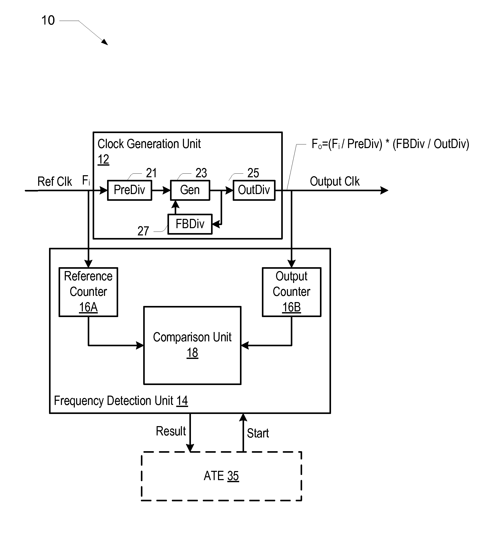
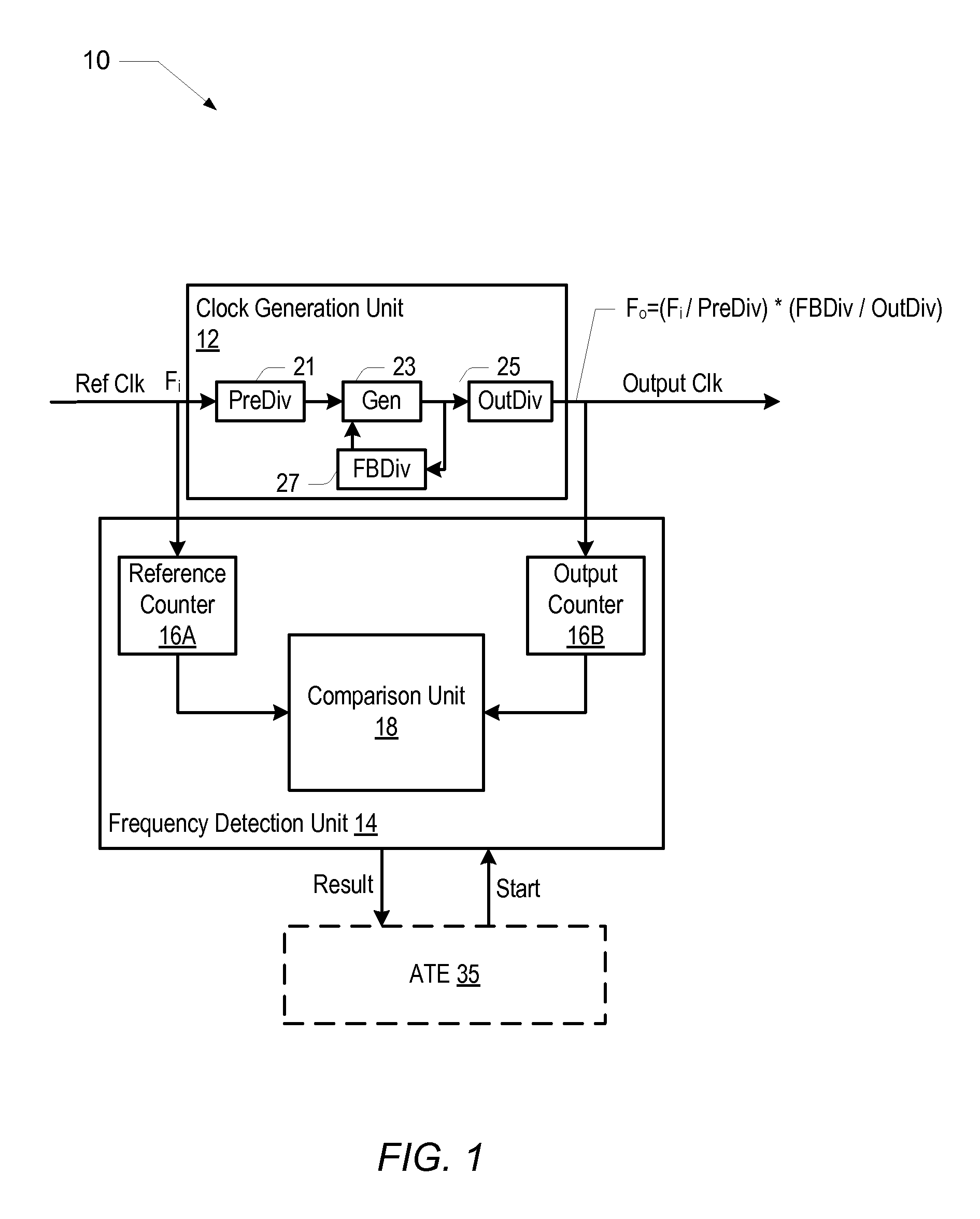
[0018]Turning now to FIG. 1, a block diagram of one embodiment of an integrated circuit including a frequency detection unit is shown. The integrated circuit 10 includes a clock generation circuit 12 coupled to a frequency detection unit 14. The clock generation unit 12 is coupled to receive a reference clock signal designated as Ref Clk, and to provide the output clock signal designated as Output Clk. The frequency detection unit 14 is coupled to receive a start signal and to provide a result. It is noted that components having a reference designator that includes a number and a letter may be referenced by the number alone, where appropriate.

[0019]In the illustrated embodiment, the clock generation unit 12 includes a PreDiv unit 21 that is coupled to a Gen unit 23, which is coupled to an OutDiv unit 25 and to the FBDiv unit 27. The FBDiv unit 27 is coupled back to the Gen unit 23 in a feedback loop. The OutDiv unit 25 is configured to provide the Output Clk signal. The PreDiv unit ...


PUM


Abstract

A frequency detection mechanism for a clock generation unit on an integrated circuit includes a clock generation unit and a detection unit. The clock generation unit may generate an output clock signal at a predetermined frequency that corresponds to a frequency multiple of a reference clock signal provided as an input to the clock generation unit. The detection unit may determine whether the output clock signal is at the predetermined frequency. As such, the detection unit includes a first counter that may generate a first count value based upon the reference clock signal and a second counter that may generate a second count value based upon the output clock signal. The detection unit also includes comparison logic that may perform a plurality of multiplication operations on the first and second count values and generate a final result that indicates whether the output clock signal is at the predetermined frequency.

Description

[0001]This application is a continuation of U.S. patent application Ser. No. 12 / 732,959, entitled “A Frequency Detection Mechanism For A Clock Generation Circuit,” filed Mar. 26, 2010, which is herein incorporated by reference in its entirety.BACKGROUND[0002]1. Technical Field[0003]This disclosure relates to frequency detection and, more particularly, to frequency detecting mechanisms for clock generation circuits.[0004]2. Description of the Related Art[0005]Many types of electronic systems use clock generation circuits to generate clock signals. Some clock generation circuits use a reference clock to generate higher or lower frequency clock signals. One such circuit is referred to as a phase locked loop (PLL) circuit. An analog PLL typically includes a feedback path. If the PLL is used as a frequency multiplier, the feedback path includes a divider. A reference clock is mixed with the feedback signal to feed a phase detector. The output of the phase detector may be low pass filtere...

Claims


Application Information

Patent Timeline
Patent Type & Authority Applications(United States)
IPC IPC(8): G06F1/04G01R23/02
CPCG06F1/04G01R23/15
Inventor MURRAY, DANIEL C.
Owner APPLE INC
Why Eureka
Try Eureka