
Information processing system, printing apparatus, and information processing method

a technology of information processing system and printing apparatus, which is applied in the direction of fault response, digital output to print units, instruments, etc., can solve the problems of increasing control load, giving the user a feeling of annoyance, and difficult for the user to determine whether multiple errors have occurred in the printing apparatus

Active Publication Date: 2012-01-26
SEIKO EPSON CORP
View PDF0 Cites 12 Cited by
  • Summary
  • Abstract
  • Description
  • Claims
  • Application Information

AI Technical Summary

Benefits of technology

[0012]An advantage of some aspects of the invention is that an information processing system, a printing apparatus, and an information processing method that can prevent multiple pieces of error information with identical output contents from being output from an output unit are provided.

Problems solved by technology

However, since an increasing number of print heads leads to an increase in the control load of the main controller, the main controller itself may conceivably be constituted of multiple print controllers (information processing devices).
Therefore, it is difficult for the user to determine whether multiple errors have occurred in the printing apparatus or only a single error has occurred in the printing apparatus by simply visually checking the first display region 201.
This may possibly give the user a feeling of annoyance with regard to the display mode on the monitor 200.
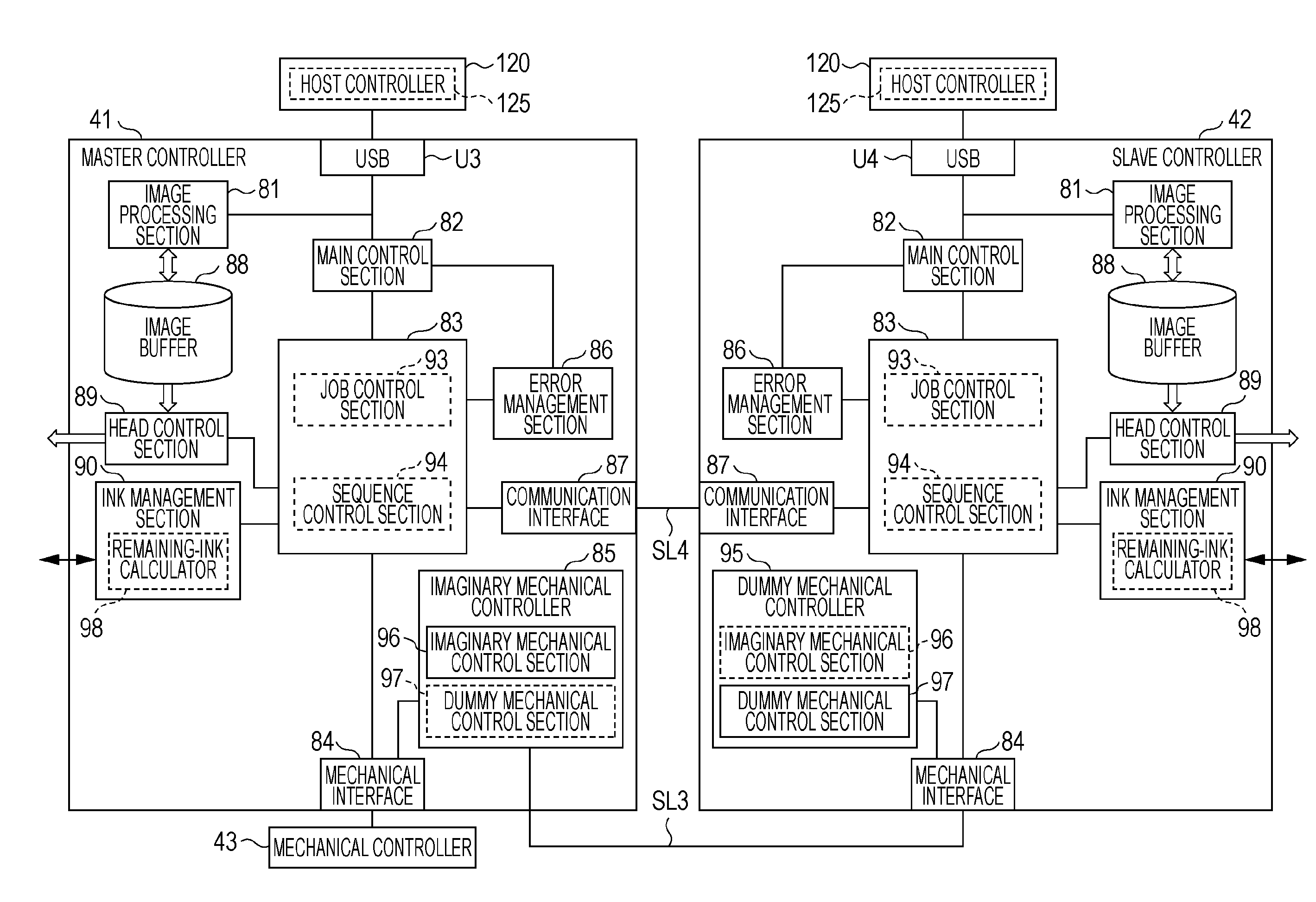
When an error in the drive control device or an error in the mechanical mechanism is detected, the drive control device outputs error occurrence information to each information processing device.
Because the data length of an error command not including an identification code changes depending on the number of error occurrence locations, it is difficult for the output control apparatus to analyze the input error command.

Method used


Image

  • Information processing system, printing apparatus, and information processing method
  • Information processing system, printing apparatus, and information processing method
  • Information processing system, printing apparatus, and information processing method

Examples


first embodiment

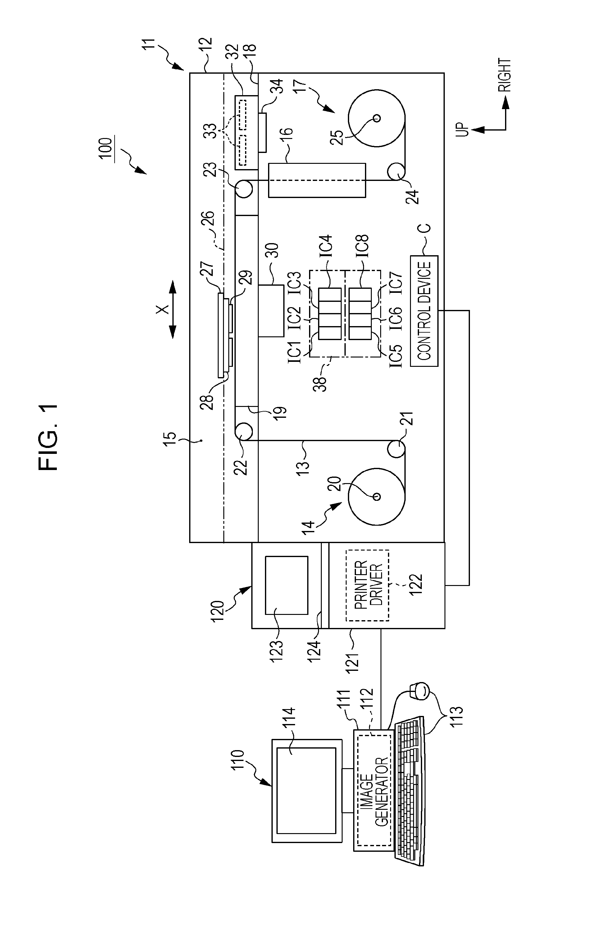
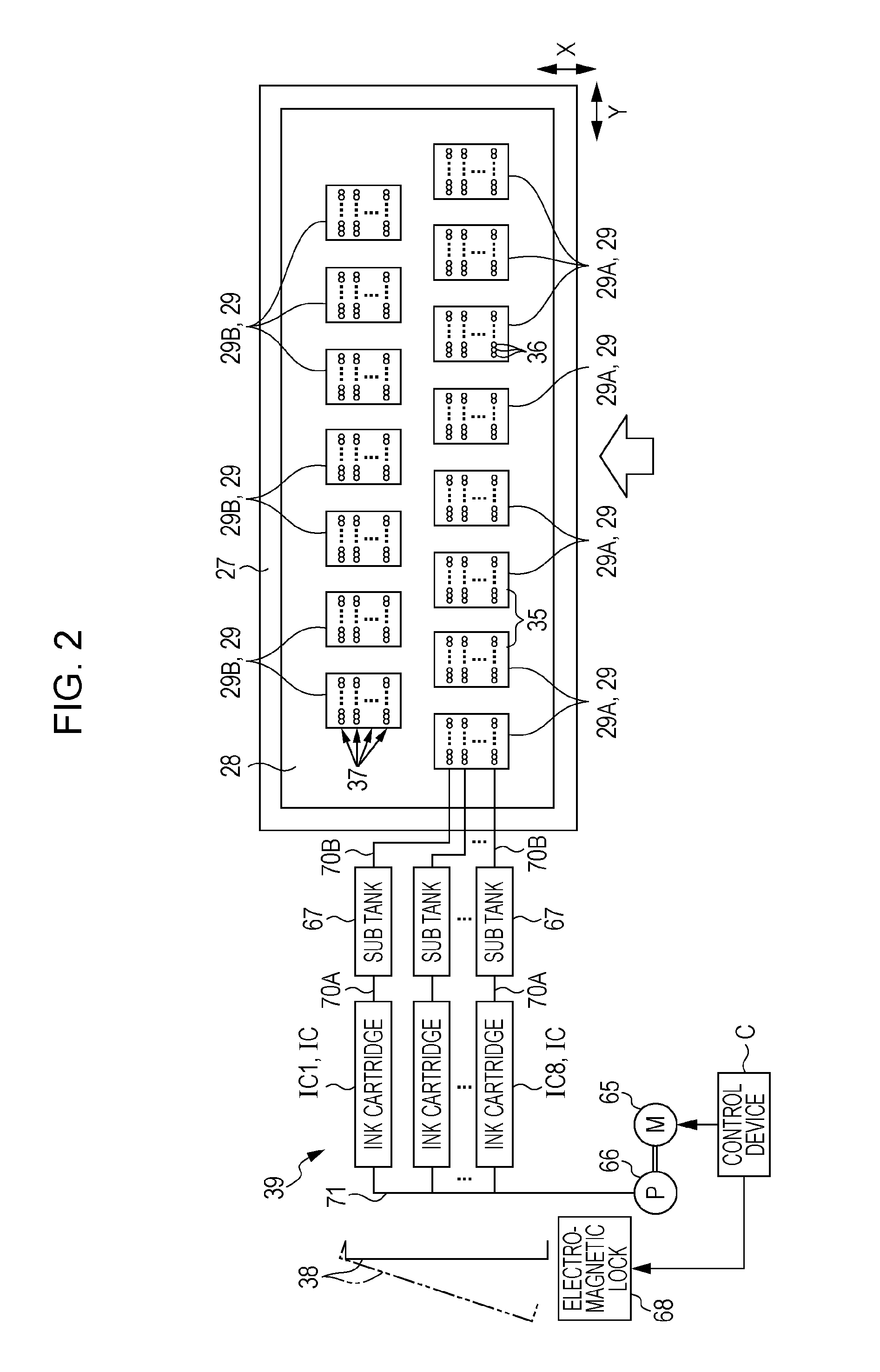
[0054]An information processing system of a lateral-type ink jet printer according to a first embodiment of the invention will be described below with reference to FIGS. 1 to 11.

[0055]FIG. 1 schematically illustrates a printing system equipped with the lateral-type ink jet printer. As shown in FIG. 1, a printing system 100 includes an image generating apparatus 110 that generates image data, a host apparatus 120 that generates print data on the basis of the image data received from the image generating apparatus 110, and a lateral-type ink jet printer (sometimes simply referred to as “printer” hereinafter) 11 serving as a printing apparatus that prints an image based on the print data received from the host apparatus 120.

[0056]The image generating apparatus 110 is, for example, a personal computer and includes an image generator 112 that causes a central processing unit (CPU) within a main body 111 of the personal computer to execute an image generating software program. A user may ...

second embodiment

[0157]Next, a second embodiment according to the invention will be described with reference to FIGS. 12 to 16. The second embodiment differs from the first embodiment in how an error command is generated at each of the controllers 41 and 42. Therefore, the following description will mainly include descriptions of parts that differ from those in the first embodiment. Components that are the same as or equivalent to those in the first embodiment are given the same reference numerals, and redundant descriptions thereof will be omitted.

[0158]As shown in FIG. 12, the error management section 86 in each of the controllers 41 and 42 has an identification-information storage portion 86a. The identification-information storage portion 86a stores a table T2 shown in FIG. 13. As shown in FIG. 13, the table T2 is used for determining whether or not it is necessary to identify which one of the controllers 41 and 42 has detected an error for each error code (i.e., for each error content). In this...


PUM


Abstract

Each of controllers includes an error management section that generates an error command including an error code indicating the content of an error when the controller detects the error. A host apparatus includes a host controller. If the error command from the master controller and the error command from the slave controller are identical to each other, the host controller displays a single piece of error information on a monitor. Specifically, the single piece of error information includes the error code included in the error command and an error message corresponding to the error code.

Description

[0001]This application claims priority to Japanese Patent Application No. 2010-163652, filed Jul. 21, 2010, the entirety of which is incorporated herein by reference.BACKGROUND[0002]1. Technical Field[0003]The present invention relates to an information processing system and an information processing method for controlling an output mode to be output from an output unit. The invention also relates to a printing apparatus equipped with such an information processing system.[0004]2. Related Art[0005]In the related art, JP-A-2004-25551 proposes a printing apparatus as an example of a large-size printing apparatus that performs printing on a print medium. This printing apparatus includes a plurality of print heads and drive control units corresponding to the respective print heads. The print heads and the drive control units are mounted on a single carriage. The main body of the printing apparatus is provided with a plurality of data processors corresponding to the respective drive cont...

Claims


Application Information

Patent Timeline
Patent Type & Authority Applications(United States)
IPC IPC(8): G06F11/07B41J29/38G06F3/048
CPCB41J2/16585G06F3/12G06F3/121G06F3/1229G06K15/408G06F11/3013G06F11/327G06K15/402G06F3/1285
Inventor MIURA, HIROTSUNA
Owner SEIKO EPSON CORP
Learn More