Control of a loudspeaker output

a technology of output and loudspeaker, which is applied in the direction of transducer protection circuits, electrical devices, etc., can solve the problems of reducing the expected life of the loudspeaker, affecting the sound quality of the loudspeaker, so as to achieve better and more rapid response and improve sound pressure

Active Publication Date: 2012-01-26
GOODIX TECH HK CO LTD
View PDF1 Cites 34 Cited by
  • Summary
  • Abstract
  • Description
  • Claims
  • Application Information

AI Technical Summary

Benefits of technology

[0026]During subsequent use of the loudspeaker, taking measurements to enable monitoring of the loudspeaker impedance can comprise generating an evaluation signal, and combining an input sound signal with the evaluation signal. The evaluation signal enables the measurements to be taken even if there is no (or an insufficient) speaker signal being generated in response to the audio input signal.
[0027]Generating an evaluation signal and combining it with the input sound signal thus ensures that the loudspeaker signal comprises a signal suitable for evaluation, i.e. a signal which has sufficient energy in the frequencies which are monitored and used for adapting the loudspeaker signal. When adapting the loudspeaker signal to respond to the measured temperature, this is in particular in dependency on the monitored response to the evaluation signal. In this way, a continuous monitoring of the temperature of the voice coil is possible, allowing a better and more rapid response. For example, during a period in which the input sound signal comprises insufficient energy for other methods to determine the temperature of the voice coil, the voice coil may cool down. A cooled down voice coil allows the sound pressure to increase somewhat, and needs to be detected so that the adaptation of the audio input signal can be correctly modified. The evaluation signal preferably has a particular evaluation frequency, so that frequency-based analysis is used to obtain the measurements.

Problems solved by technology

For example, an important cause of loudspeaker failures is a mechanical defect that arises when the loudspeaker diaphragm is displaced beyond a certain limit, which is usually supplied by the manufacturer.
Going beyond this displacement limit either damages the loudspeaker immediately, or can considerably reduce its expected life-time.
However, much of the electrical power that is applied to the loudspeaker results in heat dissipation, which causes many of the common loudspeaker defects.
However, the speaker has an impedance spread caused by the speaker production process.

Method used


Image

  • Control of a loudspeaker output
  • Control of a loudspeaker output

Examples


Embodiment Construction

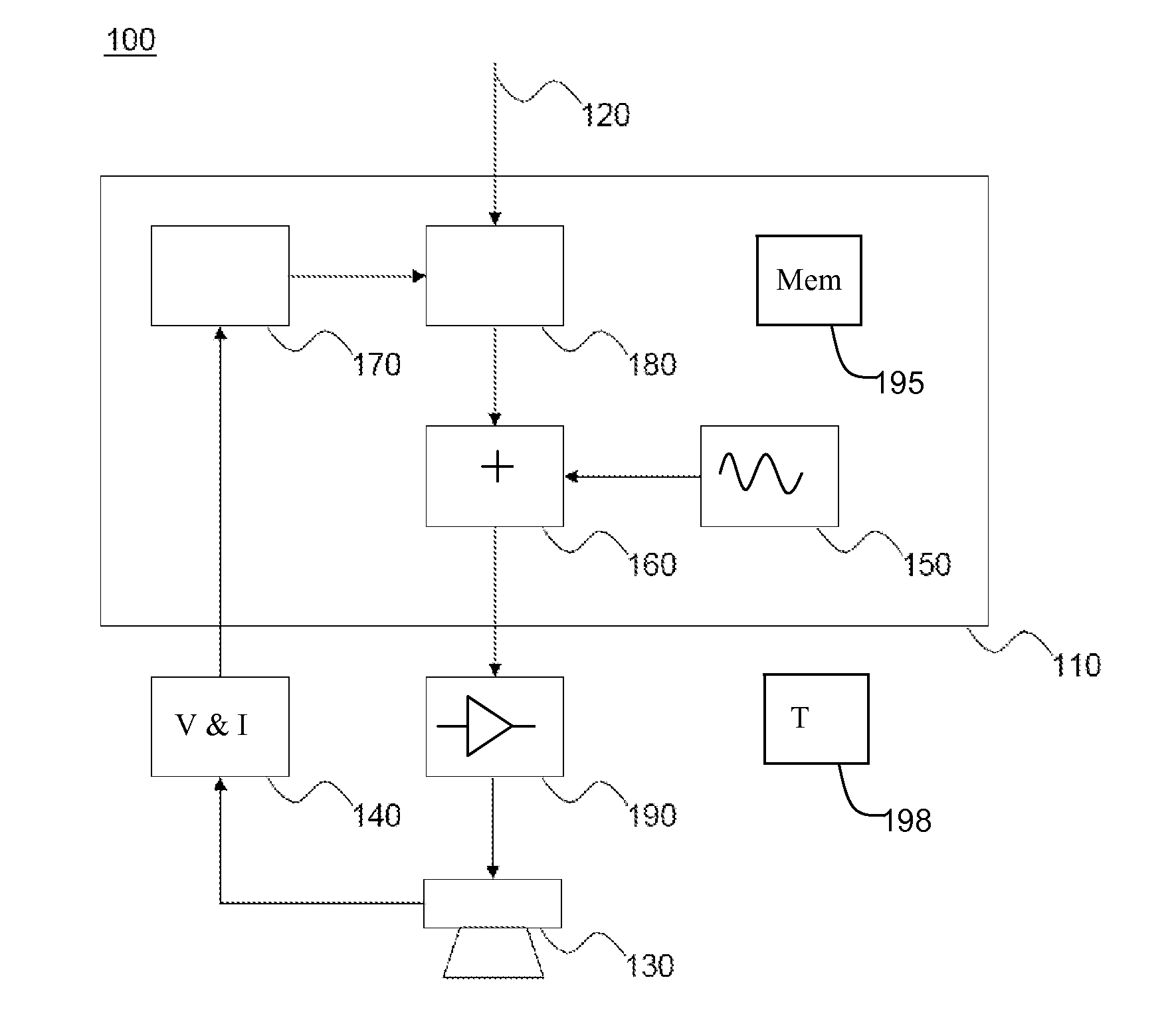
[0040]The invention provides a method of controlling a loudspeaker of an electronic device to provide voice coil temperature protection. When a power supply for the electronic device is first activated, a binding step is performed in which the loudspeaker impedance is determined and a temperature (such as ambient temperature) is accurately measured. These binding step measurements are used during subsequent use of the loudspeaker, to make the temperature measurements (based on voice coil impedance) as accurate as possible.

[0041]FIG. 1 shows in schematic form a loudspeaker control system which can be controlled in accordance with the invention.

[0042]The system 100 obtains an input sound signal 120 from a source. The signal may be received at an input to the system 100. For example, the input sound signal 120 may be obtained from a source external to the system. Input signal 120 may also be retrieved from a storage system. The input signal may be analog or digital. In an embodiment, t...


PUM


Abstract

A method of controlling a loudspeaker of an electronic device provides voice coil temperature protection. When a power supply for the electronic device is first activated, a binding step is performed in which the loudspeaker impedance is determined and a temperature (such as ambient temperature) is accurately measured. These binding step measurements are used during subsequent use of the loudspeaker, to make the temperature measurements (based on voice coil impedance) as accurate as possible.

Description

[0001]This application claims the priority under 35 U.S.C. §119 of European patent application no. 10166206.2, filed on Jun. 16, 2010, the contents of which are incorporated by reference herein.FIELD OF THE INVENTION[0002]This invention relates to the control of the output of a loudspeaker.BACKGROUND OF THE INVENTION[0003]It is well known that the output of a loudspeaker should be controlled in such a way that it is not simply driven by any input signal. For example, an important cause of loudspeaker failures is a mechanical defect that arises when the loudspeaker diaphragm is displaced beyond a certain limit, which is usually supplied by the manufacturer. Going beyond this displacement limit either damages the loudspeaker immediately, or can considerably reduce its expected life-time.[0004]It is also well known that the drive signal to the speaker should avoid thermal damage. Loudspeakers are devices which convert electrical energy into acoustical energy. However, much of the elect...

Claims


Application Information

Patent Timeline
Patent Type & Authority Applications(United States)
IPC IPC(8): H04R29/00
CPCH04R29/003H04R3/007
Inventor HUIJSER, JAN-PAULUS FREERKSOMBERG, JOHAN
Owner GOODIX TECH HK CO LTD
Why Eureka
Try Eureka