Automatic analysis device and dispensing device

Inactive Publication Date: 2012-01-26
HITACHI HIGH-TECH CORP
View PDF6 Cites 17 Cited by
  • Summary
  • Abstract
  • Description
  • Claims
  • Application Information

AI Technical Summary

Benefits of technology

[0023]The effects obtained by typical aspects of the present invention disclosed in the present application will be briefly described below.
[0024]That is, an automatic analysis device of the present invention includes: an intermediate unit on which an intermediate container for mixing a sample with pretreatment liquid or a reagent is arranged; and a plurality of analysis units for carrying out a test for the sample dispensed from the intermediate container, and therefore, the intermediate unit can be commonly used among a plurality of test items.
[0025]Also, the plurality of analysis units are separated into: a main analysis unit for carrying out a test for an item having a relatively large number of test requests, on which a reaction vessel for carrying out a reaction after the treatment is arranged; and a plurality of sub analysis units for carrying out a test for an item having a relatively small number of test requests obtained after a reaction in the intermediate container, and therefore, the test for the item having the relatively large number of test requests can be carried out without being prevented by a test for other items.
[0026]As described above, by providing the mechanism which can be commonly used among tests for respective items as ensuring the path for carrying out the test for the item having the relatively large number of test requests, the device configuration can be simplified.
[0027]Also, in the automatic analysis device of the

Problems solved by technology

However, if a system which automatically processes all of such tests carried out in a clinical laboratory is introduced, huge cost is required, and the introduction cannot be carried out in a general hospital or others.
However, the device to which a B/F separating function is added generally has a complicated mechanism, and problems such as a large device size and low processing

Method used


Image

  • Automatic analysis device and dispensing device
  • Automatic analysis device and dispensing device
  • Automatic analysis device and dispensing device

Examples


Embodiment Construction

[0076]Hereinafter, embodiments of the present invention will be explained in detail with reference to the accompanying drawings. Note that components having the same function are denoted by the same reference symbols in principle throughout the drawings for explaining the embodiments, and the repetitive description thereof will be omitted as much as possible.

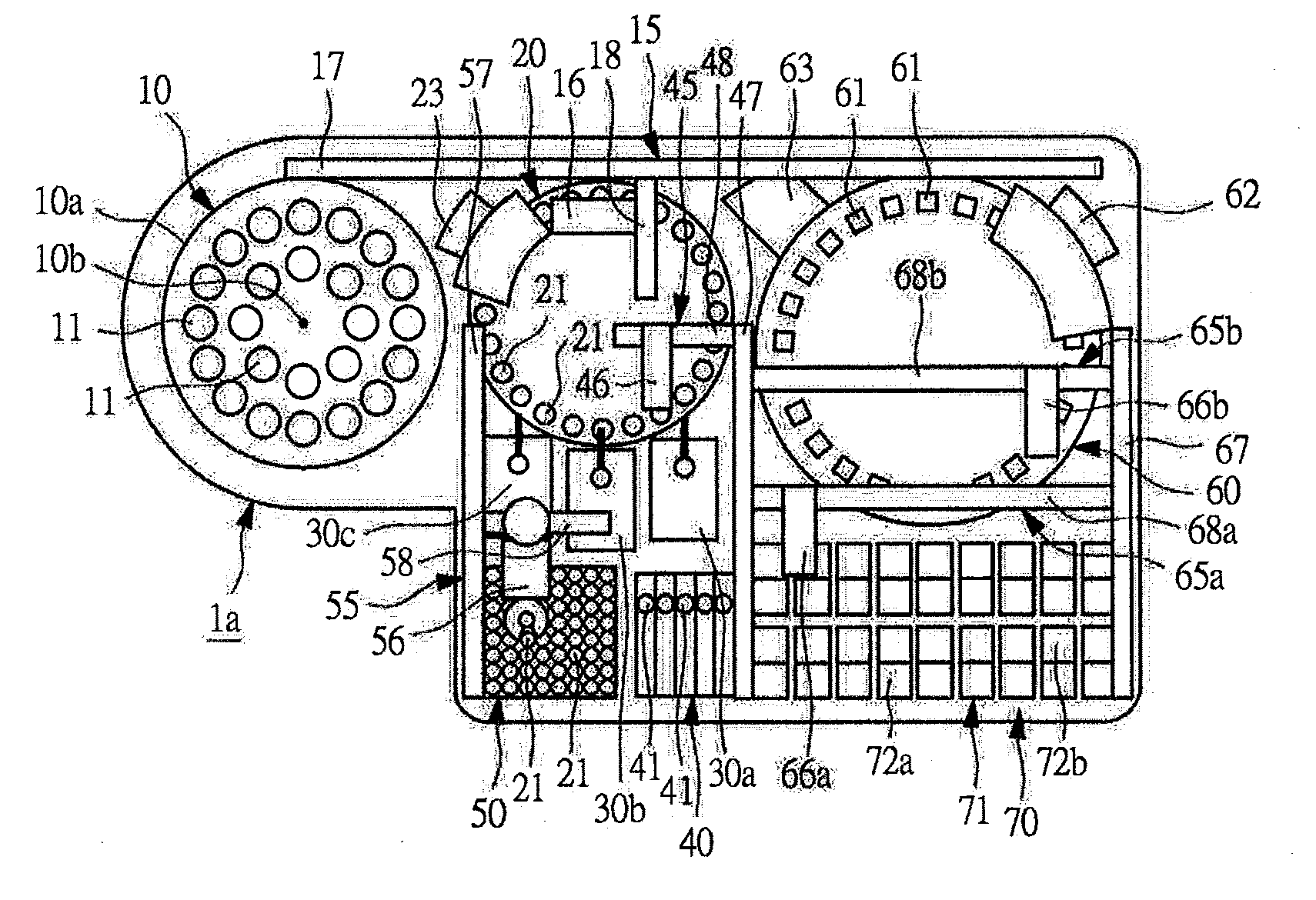
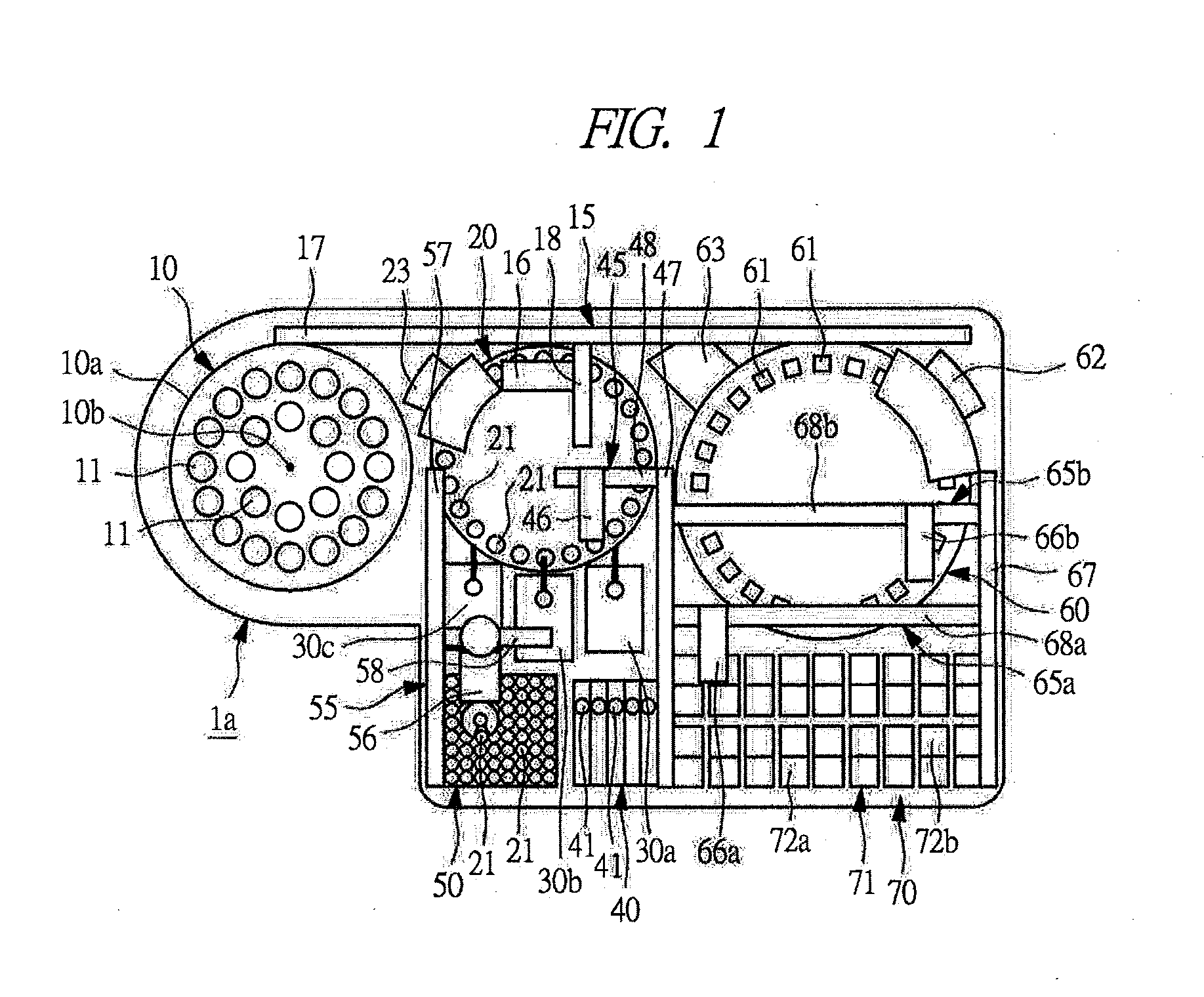
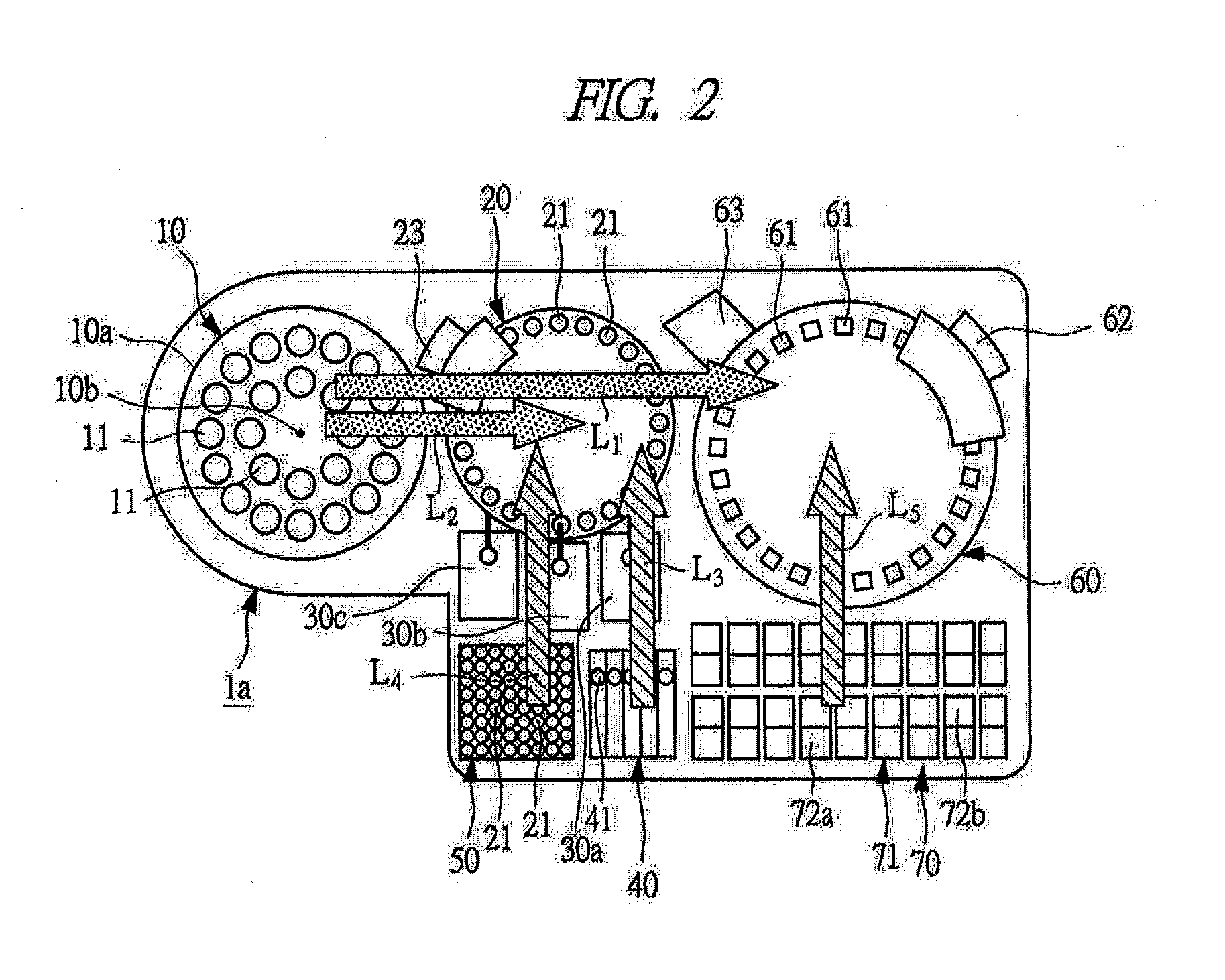
[0077]FIG. 1 is a schematic plan view showing an outline of an embodiment of an automatic analysis device of the present invention, and FIG. 2 is a view showing flows of a sample, pretreatment liquid, a reagent, and others in the automatic analysis device of FIG. 1. FIGS. 3A to 3C, FIGS. 4A to 4C, and FIGS. 5A to 5C are explanatory views each explaining an example of an operation flow in the automatic analysis device of FIG. 1 in this order. FIG. 6 is an explanatory view explaining another example of the operation flow in the automatic analysis device of FIG. 1. Note that, in FIG. 2, the showing of the sample dispensing mechanis...


PUM


Abstract

An automatic analysis device 1a includes: an intermediate disk (intermediate unit) 20 on which a disposable container (intermediate container) 21 for carrying out a pretreatment by pretreatment liquid for a sample dispensed from a sample container 11 or a reaction with a reagent is arranged; a reaction disk (main analysis unit) 60 for carrying out a test of an item having a relatively large number of test requests, on which a reaction vessel 61 for carrying out a reaction of a reagent with the sample obtained after the pretreatment is arranged; and flow-based analysis mechanisms (sub analysis units) 30a to 30c for carrying out a test for the sample obtained after the reaction with the reagent in the disposable container 21, which is the item having a relatively small number of test requests.

Description

TECHNICAL FIELD[0001]The present invention relates to an automatic analysis device which automatically analyzes a component of blood or others, and more particularly, the present invention relates to a technique effectively applied to a device which carries out a test for a plurality of items such as a biochemical test, an immunoserological test, and a blood coagulation test.BACKGROUND ART[0002]In a clinical laboratory test, various pretreatments such as centrifugal separation, hemolysis, and B / F separation of an antigen-antibody reaction in an immunoserological test are required. These pretreatments are not carried out in an automatic analysis device which actually carries out the tests, but are previously carried out in a dedicated device in many cases.[0003]As the device which previously carries out the pretreatments, a specimen conveying system is well known. In the specimen conveying system, a pretreatment unit and a plurality of analysis devices are connected by a belt conveyo...

Claims


Application Information

Patent Timeline
IPC IPC(8): G01N33/50
CPCG01N35/025G01N2035/0453
Inventor MIMURA, TOMONORIMAKINO, AKIHISAADACHI, SAKUICHIRO
Owner HITACHI HIGH-TECH CORP
Why Eureka
Try Eureka