Dual Chamber Passive Retraction Needle Syringe

a passive retraction and needle syringe technology, applied in the field of syringe assemblies, can solve the problems of inadvertent activation of the retraction feature, increased complexity of the sealing plunger and stopper, and device inadvertent activation

Active Publication Date: 2012-01-26
BECTON DICKINSON & CO
View PDF5 Cites 47 Cited by
  • Summary
  • Abstract
  • Description
  • Claims
  • Application Information

AI Technical Summary

Benefits of technology

[0021]In one or more embodiments of the present invention, the needle cannula is biased to move in the proximal direction by a spring disposed between the needle hub and the barrier wall that exerts a force on the needle hub and the spring is compressed when the flexible tab engages the needle hub. In one or more embodiments of the present invention, the needle chamber barrier wall further comprises a second aperture to permit the flexible tab to flex inwardly into the needle chamber and a ramped portion that extends outwardly into the fluid chamber. In one or more embodiments of the present invention, the disengagement of the flexible tab and the needle hub permits the spring to expand and causes the needle hub to retract into the hollow interior of the trigger element.
[0022]In one or more embodiments of the present invention, the trigger element is disposed on the plunger rod body and extends radially outwardly from the plunger rod body. In one or more embodi

Problems solved by technology

Accordingly, such retraction features require cutting, braking, piercing or other force-intensive mechanical action for activation and, thus, increased complexity to enable the sealed plunger and stopper to be breached during activation.
Further, as most conventionally designed retractable needles are activated after dosing by continued pressure on the rear of the plunger rod, inadvertent activation of the retraction feature may occur since the same forces must be applied when expelling the contents of the syringe barrel.
Moreover, some devices may be inadvertently activated during dosing if sufficient pressure is generated during expulsion of the contents of the syringe, for example, when the medication is viscous and requires the user to apply additional pressure or force to the plunger rod, which exceeds the force required to activate the retraction feature.
Premature activation is especially problematic in applications where high forces are applied to the plunge rod, for example, during high speed injections.
The threshold force may be difficult to ascertain and maintain separately from the force applied to the plunger rod to expel the contents of the syringe barrel.
The additional force required to activate the retraction feature may cause additional pressure to be generated at the stopper or other remov

Method used


Image

  • Dual Chamber Passive Retraction Needle Syringe
  • Dual Chamber Passive Retraction Needle Syringe
  • Dual Chamber Passive Retraction Needle Syringe

Examples


Embodiment Construction

[0052]Before describing several exemplary embodiments of the invention, it is to be understood that the invention is not limited to the details of construction or process steps set forth in the following description. The invention is capable of other embodiments and of being practiced or being carried out in various ways.

[0053]In this disclosure, a convention is followed wherein the distal end of the device is the end closest to a patient and the proximal end of the device is the end away from the patient and closest to a practitioner.

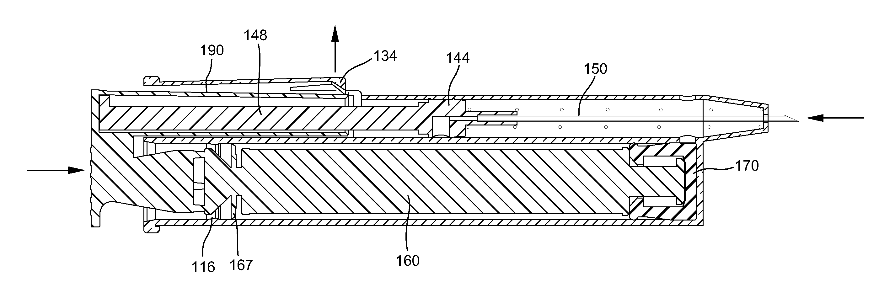
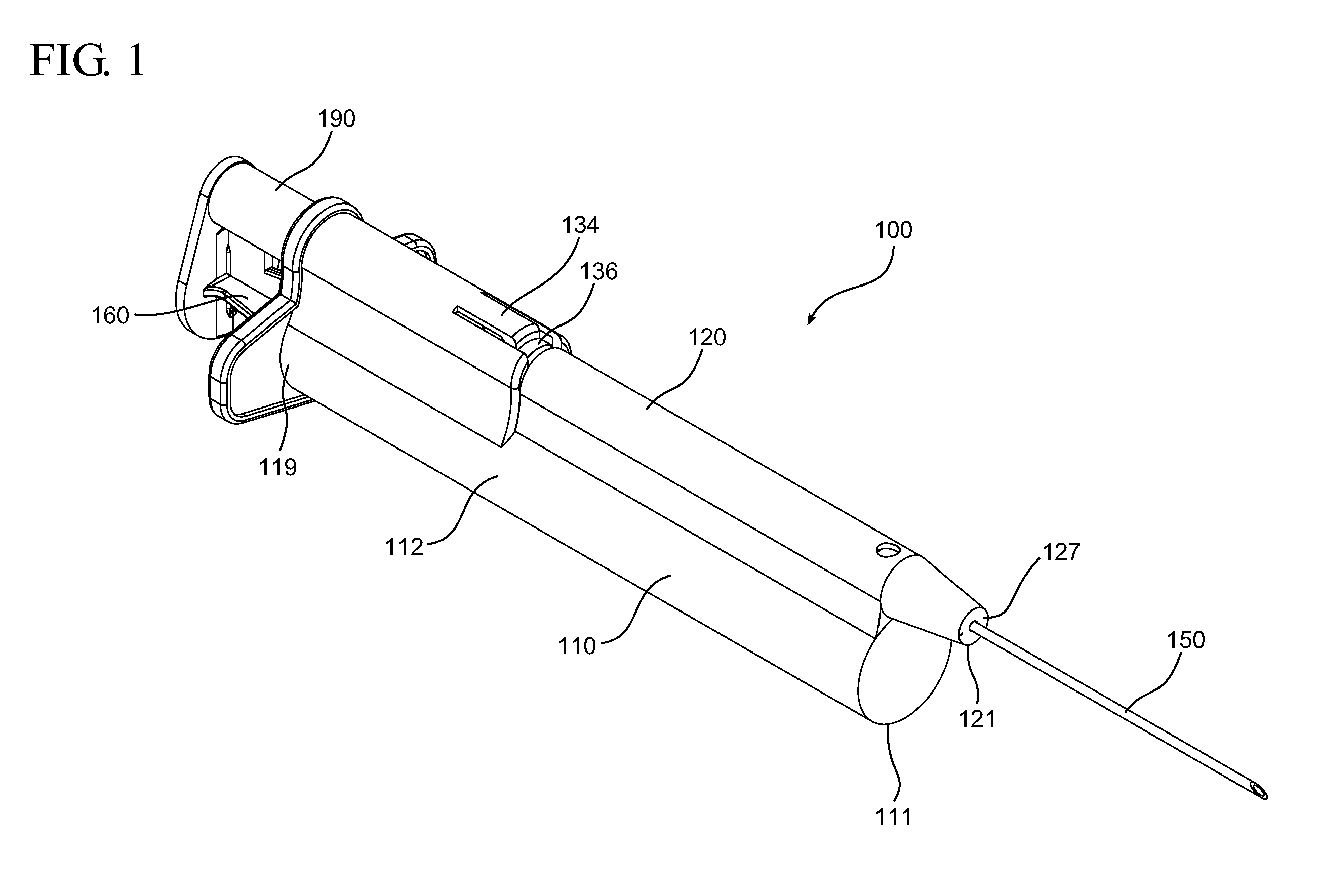
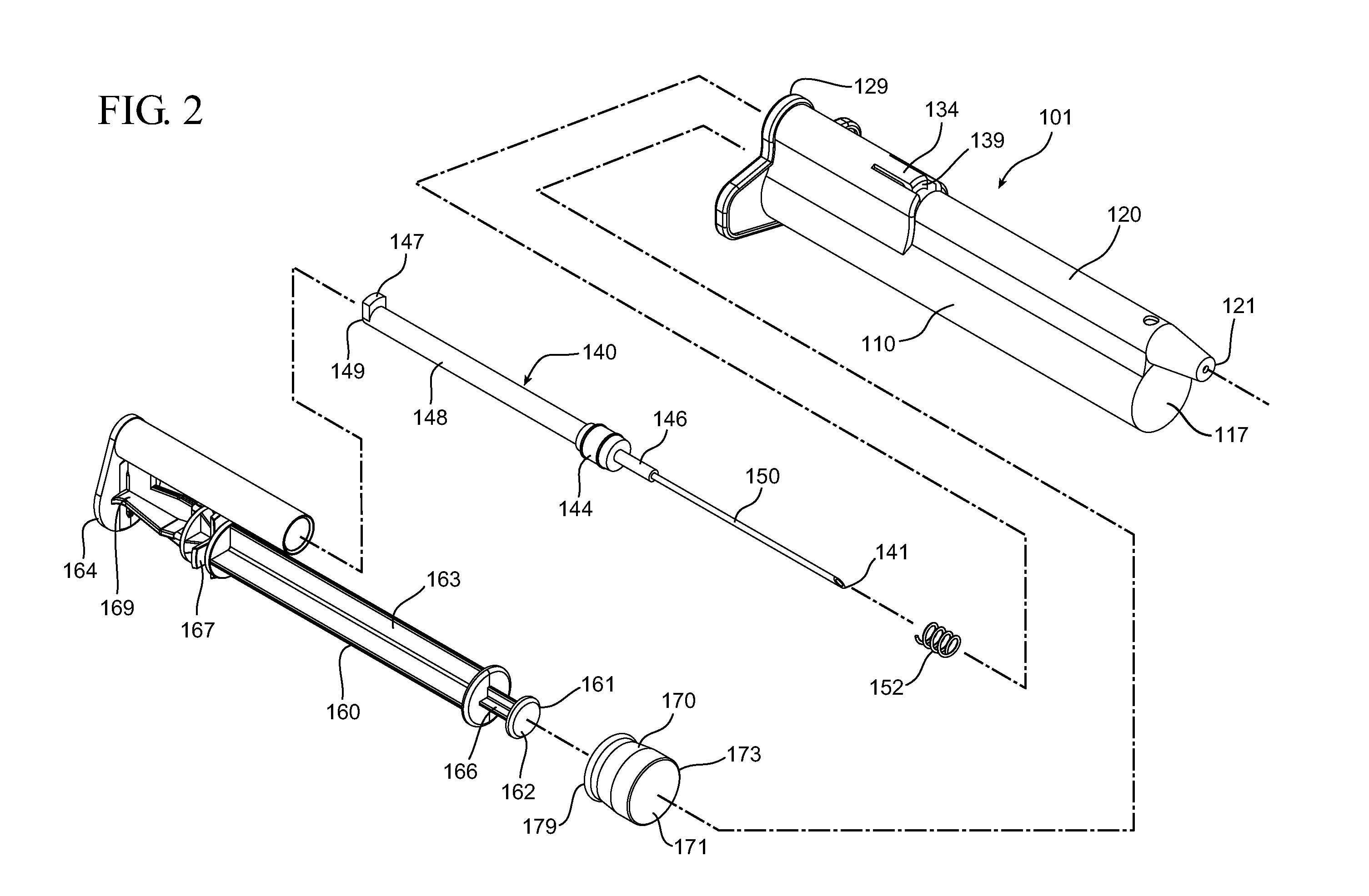
[0054]A first aspect of the present invention pertains to a retractable syringe assembly having a passive retraction feature. The retractable syringe assembly 100 of one or more embodiments utilizes a dual syringe barrel or a syringe barrel that isolates the fluid chamber from the retraction feature.

[0055]In the embodiment shown in FIGS. 1-11, the retractable syringe assembly includes a dual syringe barrel 101 that includes fluid barrel 110 and a retra...


PUM


Abstract

Embodiments of a retractable syringe assembly are provided that include a dual syringe barrel configuration. In one or more embodiments, the assemblies include a fluid barrel for retaining fluid and a retraction barrel for housing the retraction feature and the needle hub assembly. The assemblies include a trigger element that moves with the plunger rod to activate the retraction feature within the retraction mechanism.

Description

CROSS-REFERENCE TO RELATED APPLICATIONS[0001]This application claims priority under 35 U.S.C. §119(e) to U.S. Provisional Application No. 61 / 366,749, filed Jul. 22, 2010, the disclosures of which are incorporated herein by reference in their entirety.TECHNICAL FIELD[0002]Aspects of the present invention relate to syringe assemblies that include a retractable needle and reuse prevention features and methods of using such syringe assemblies.BACKGROUND[0003]Needle retraction features have been incorporated into syringe assemblies to protect users from needle stick injuries. In conventional assemblies, the needle hub assemblies including a needle cannula, are attached to the syringe barrel and must be withdrawn into the syringe barrel by a user or by a retraction feature. Alternatively, a needle shield may be placed over the needle cannula by the user or otherwise.[0004]In conventional syringe assemblies in which the needle hub assemblies are retracted into the syringe barrel by a retra...

Claims


Application Information

Patent Timeline
IPC IPC(8): A61M5/32
CPCA61M5/31511A61M5/3234A61M2005/3235A61M5/5066A61M2005/3227A61M5/502A61M5/3293
Inventor ZIVKOVIC, IVANCOLE, RUSSELL
Owner BECTON DICKINSON & CO
Why Eureka
Try Eureka