Retractable needle syringe assembly

a syringe and needle technology, applied in the field of syringes and needle assemblies, can solve the problems of difficult assembly or tight tolerance requirements, premature activation of the retraction function of the syringe, and the complexity of the available retracting needle devices

Active Publication Date: 2011-08-02
BECTON DICKINSON & CO
View PDF71 Cites 23 Cited by
  • Summary
  • Abstract
  • Description
  • Claims
  • Application Information

AI Technical Summary

Benefits of technology

[0008]In another embodiment, a syringe is provided which comprises a barrel having a fluid chamber, an inside surface, a proximal end, a proximal shoulder located on the inside surface, a distal end adapted to be attached to a needle and a ceiling located on the inside surface and adjacent the distal end. According to this embodiment, the syringe further comprises a plunger rod having a distal end and a proximal end, the plunger rod adapted to slidingly engage the inside surface of the fluid chamber, the plunger rod including a hollow outer housing defined by a wall and a hollow inner sleeve slidably receivable within the outer housing and defining a cavity, and a stopper located on the distal end of the plunger rod, the stopper including a distal face and an outer wall surface. The outer housing includes at least one window extending axially through the wall adjacent the proximal end of the plunger rod, and the inner sleeve includes at least one flexible finger adapted to be flexed inwardly towards the cavity, the flexible finger including a distal end, a proximal end, a distal facing ramp surface adapted to engage with the shoulder of the barrel and a distal facing edge. The inner sleeve further includes a proximal facing stop edge, the finger being sized and shaped to be received within the window, the stopper including a distal rib, a proximal rib and a gap region between the ribs located along the outer wall surface, wherein the configuration of the ramp surface and the stopper is such that axial compression of the stopper permits sufficient axial movement of the plunger rod so that ramp surface engages the shoulder of the barrel, causing inward deflection of the fingers and relative movement of the inner sleeve and outer housing and retraction of the needle.

Problems solved by technology

In addition, in view of the fact that current conventional syringes are often manufactured at rates of several hundred per minute and their cost is generally not a significant factor in their usage, retractable syringes must be cost-effective to manufacture.
Most of the available retracting needle devices are somewhat complex, and many require manufacture and assembly of parts with potentially difficult assembly or tight tolerance requirements.
Also, if the tolerances between the multiple components of the device are not carefully adhered to during manufacture and assembly, normal usage may result in premature activation of the retraction function of the syringe.
The problem of premature activation of the retraction function is a problem with many available retracting needle syringes, particularly those that rely upon application of compressive force on the syringe stopper to activate the retraction mechanism.
Many of the available retracting needle syringes have substantial undeliverable “dead volumes” that confound the practitioners need for accurate delivery of medicaments from the syringe or that may waste a substantial percentage of a high cost medicament that is left in the dead volume space.
The problem of dead volumes may be associated with a syringe that relies on displacement of the plunger rod with respect to the syringe barrel.

Method used


Image

  • Retractable needle syringe assembly
  • Retractable needle syringe assembly
  • Retractable needle syringe assembly

Examples


Embodiment Construction

[0046]While this invention is satisfied by embodiments in many different forms, there are shown in the drawings and herein described in detail, embodiments of the invention with the understanding that the present disclosure is to be considered as exemplary of the principles of the present invention and is not intended to limit the scope of the invention to the embodiments illustrated. The invention is capable of other embodiments and of being practiced or carried out in various ways.

[0047]In this disclosure, a convention is followed wherein the distal end of the device is the end closest to a patient and the proximal end of the device is the end away from the patient and closest to a practitioner.

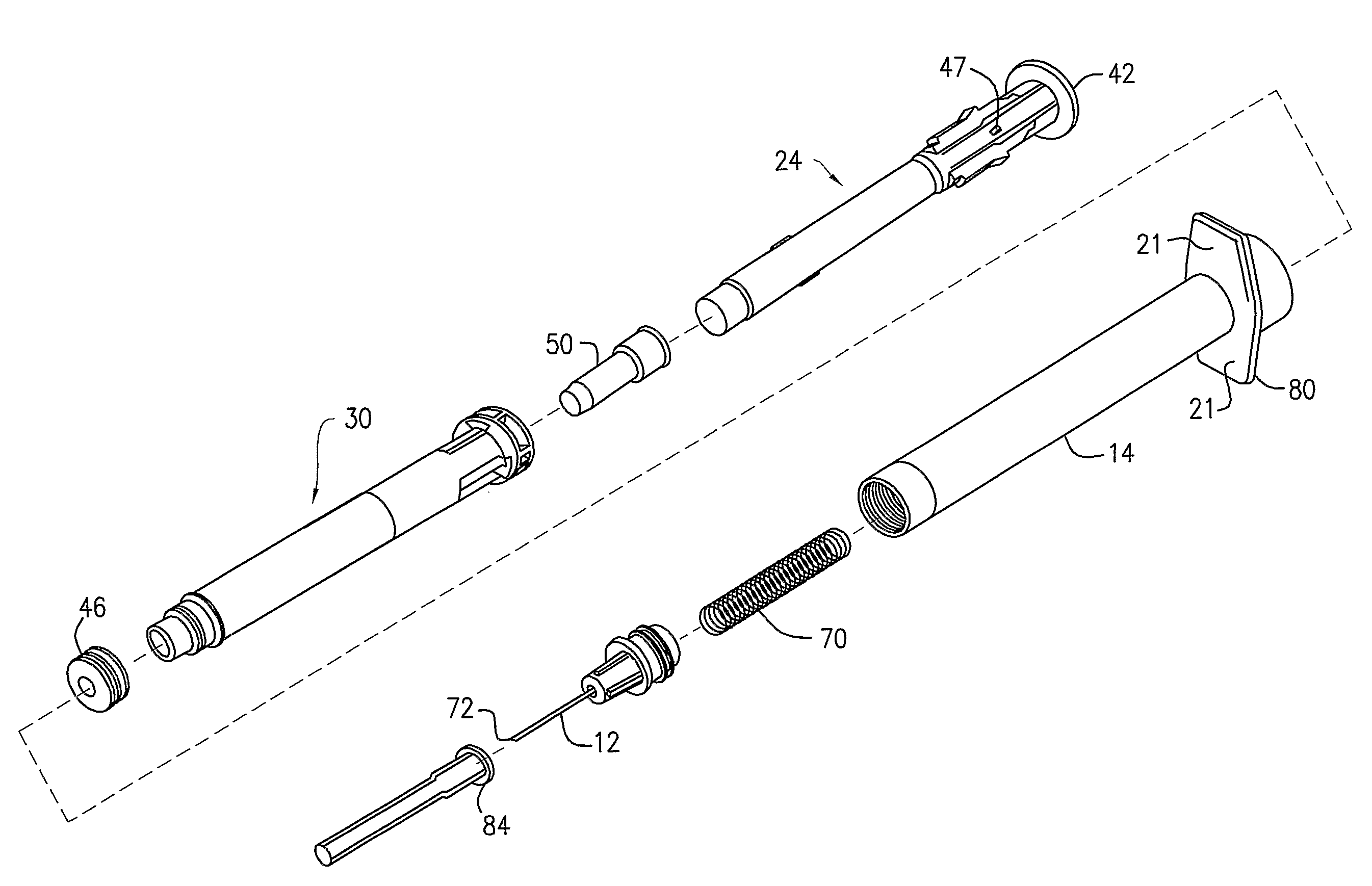
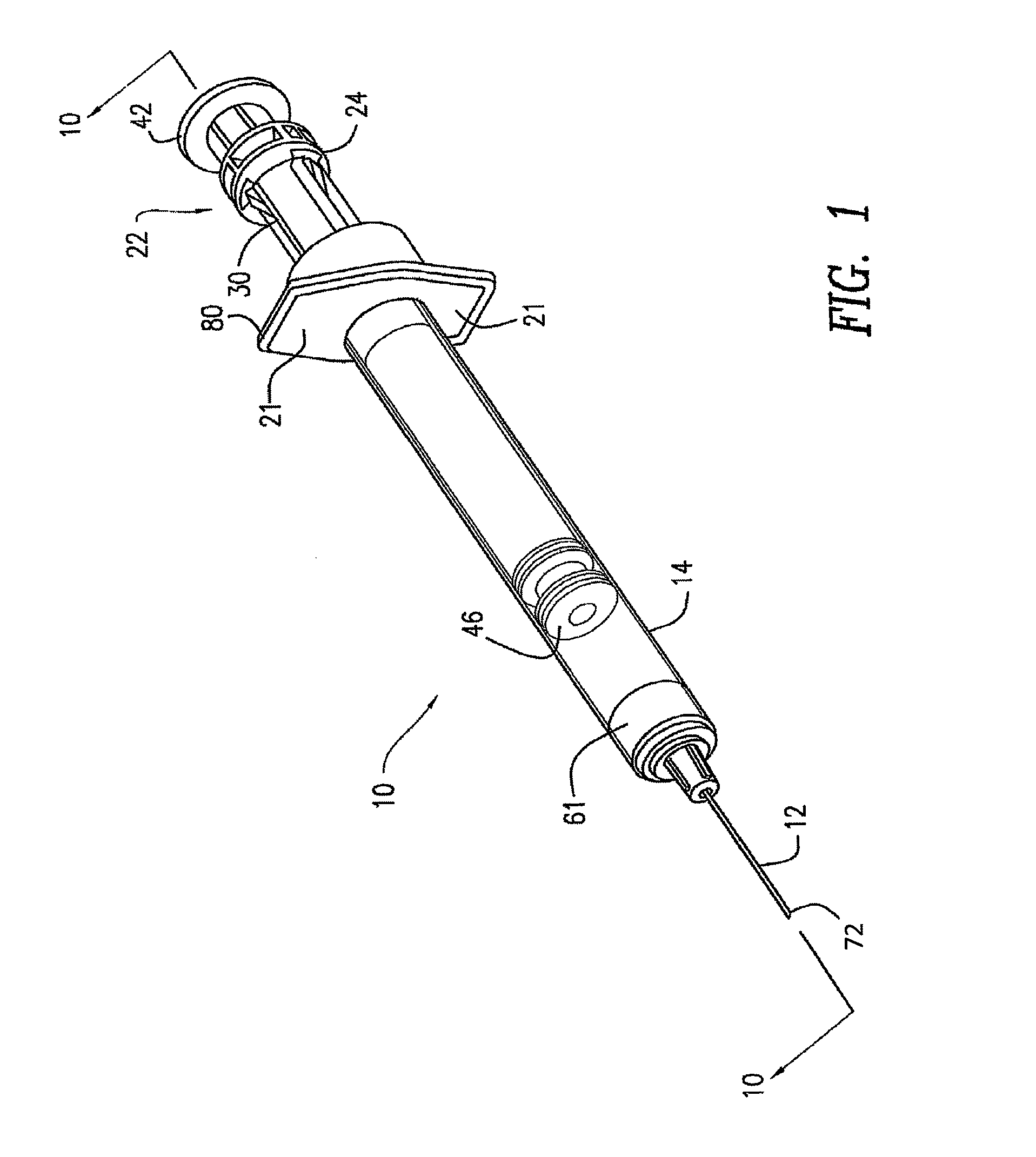
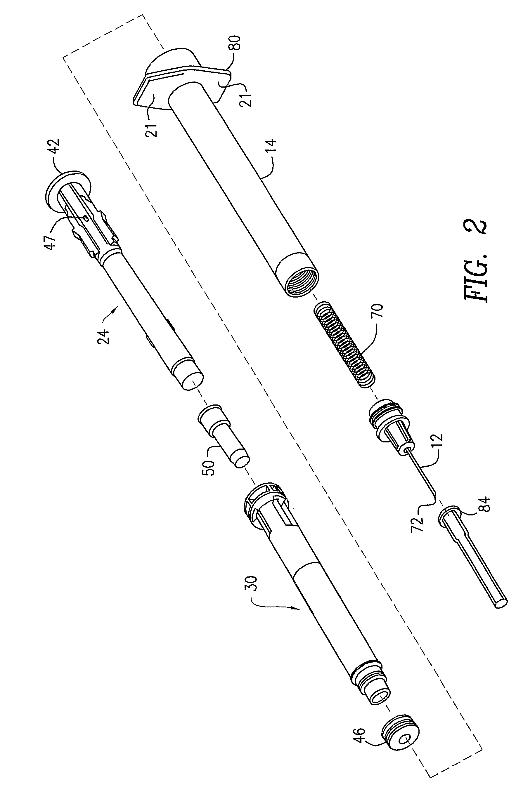
[0048]Referring generally to FIGS. 1-24, an embodiment of a hypodermic syringe 10 with a selectively retractable needle 12 according to the present invention is shown. Referring first to FIGS. 1-4C, the syringe 10 includes an elongate barrel 14 having an open proximal end 16, an open distal...


PUM


Abstract

A syringe including a barrel (14), a retractable needle (12) and a plunger rod assembly (22) including inner (30) and outer (24) members with a stopper (46) for expelling fluids from the syringe is disclosed. An activation member (40, 44) associated with the plunger rod permits relative movement of the inner and outer members when activated. The stopper is configured to compress a sufficient amount when advanced distally in the barrel to cause the activation element to engage and cause retraction of the needle within the syringe.

Description

TECHNICAL FIELD[0001]Embodiments of the present invention generally relate to syringes and needle assemblies. Specific embodiments of the invention more particularly relate to syringe assemblies that include a needle that is retractable after the intended use to substantially prevent inadvertent exposure to the needle and reuse of the syringe and methods for manufacturing needle assemblies.BACKGROUND ART[0002]Hypodermic syringes are widely used in the medical arts for administering medicaments and for drawing body fluid samples. Generally, hypodermic syringes include a fixedly or removably attached metal needle that has a sharpened distal point for penetrating vial stoppers or a patient's skin. Hypodermic syringes and needles have been used for many years with few problems reported, taking into consideration the vast numbers and needles used. More recently, with the recognition of viral diseases that are transmitted by body fluids and greater sensitivity of the need to protect healt...

Claims


Application Information

Patent Timeline
Patent Type & Authority Patents(United States)
IPC IPC(8): A61M5/00
CPCA61M5/508A61M5/3234A61M5/347
Inventor SCHILLER, ERIC R.D'ARRIGO, CHRISTINA J.PADDOCK, DOUGLAS
Owner BECTON DICKINSON & CO
Why Eureka
Try Eureka