
Method for controlling a vehicle

a technology for controlling a vehicle and a control system, applied in the direction of machinery control, instruments, process and machine control, etc., can solve the problems of insufficient system, insufficient locking effect, and insufficient traction, and achieve the effect of sufficient traction

Inactive Publication Date: 2006-03-21
CONTINENTAL TEVES AG & CO OHG
View PDF14 Cites 17 Cited by
  • Summary
  • Abstract
  • Description
  • Claims
  • Application Information

AI Technical Summary

Benefits of technology

[0019]Equation (3) makes evident that the entire engine power can be easily consumed with a sufficiently high speed, U / t, of the spinning wheels and medium brake force, FB. When the brake forces, FB, are too small, only a negligible drive torque is provided according to equation (4). However, in extreme off-road driving situations, especially in the event of diagonal twist, a high peak torque is required at least for a short time to free the motor vehicle from the difficult situation.
[0024]According to one embodiment of the present Invention, the effect of locking partially or completely a center, front axle and / or rear axle differential is achieved with means of the vehicle control system, especially by measuring and / or modulating the brake pressure in the wheel brakes of the controlled wheels, and / or a center, front axle and / or rear axle differential is locked partially or completely with the help of a differential lock, if available.
[0027]Sufficient traction is obtained in this case by maintaining the brake pressure at the relieved wheels for a period of time to achieve a locking effect comparable to that of a differential lock until the situation of the diagonal axle twist has been overcome. In this way the above-mentioned periodic oscillation of the engine torque between the wheels of a vehicle diagonal will be safely avoided, after the axle twist was detected by the method according to the invention, by preventing any lagging of the brake pressure. The locked state of the differentials or the comparable effect of a locked state preferably is maintained for a period of time that is sufficient for moving the vehicle over the obstacle. The speed (“U / t”) of the spinning wheels is reduced by stronger braking. Thus, there is a significant increase in comfort, scraping of the wheels is basically prevented and the engine speed remains constant and relatively low. In addition, tire wear is minimized.
[0029]Increased build-up and delayed reduction of the brake pressure can be achieved in an advantageous manner by changing the pressure build-up and reduction gradients. The pressure modulation also can be changed by building up pressure quicker and reducing pressure more slowly. This can be achieved by shortening the interval time during the pressure build-up and extending the interval time when the pressure is being reduced, always keeping the pressure build-up and pressure reduction pulses unchanged or by enlarging the pressure build-up pulses and reducing the pressure reduction pulses with unchanged interval times.

Problems solved by technology

In this case, sufficient traction can only be obtained with the help of a differential lock, because practical experience has shown that the measures realized in previous TCS systems have not sufficed since usually exceedingly large slip values at the spinning wheels are tolerated.
The brake pressure on the relieved wheels is not maintained in the brakes long enough and, hence, a locking effect comparable to that of a differential lock is not achieved.
The vehicle becomes stuck.

Method used


Image

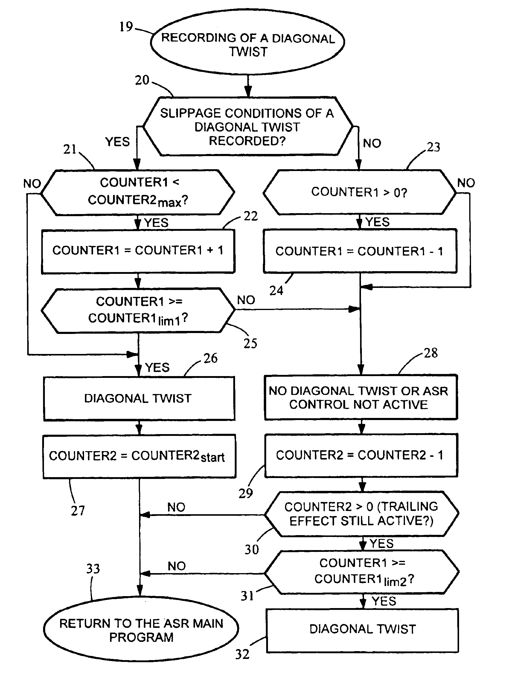
  • Method for controlling a vehicle
  • Method for controlling a vehicle
  • Method for controlling a vehicle

Examples


Embodiment Construction

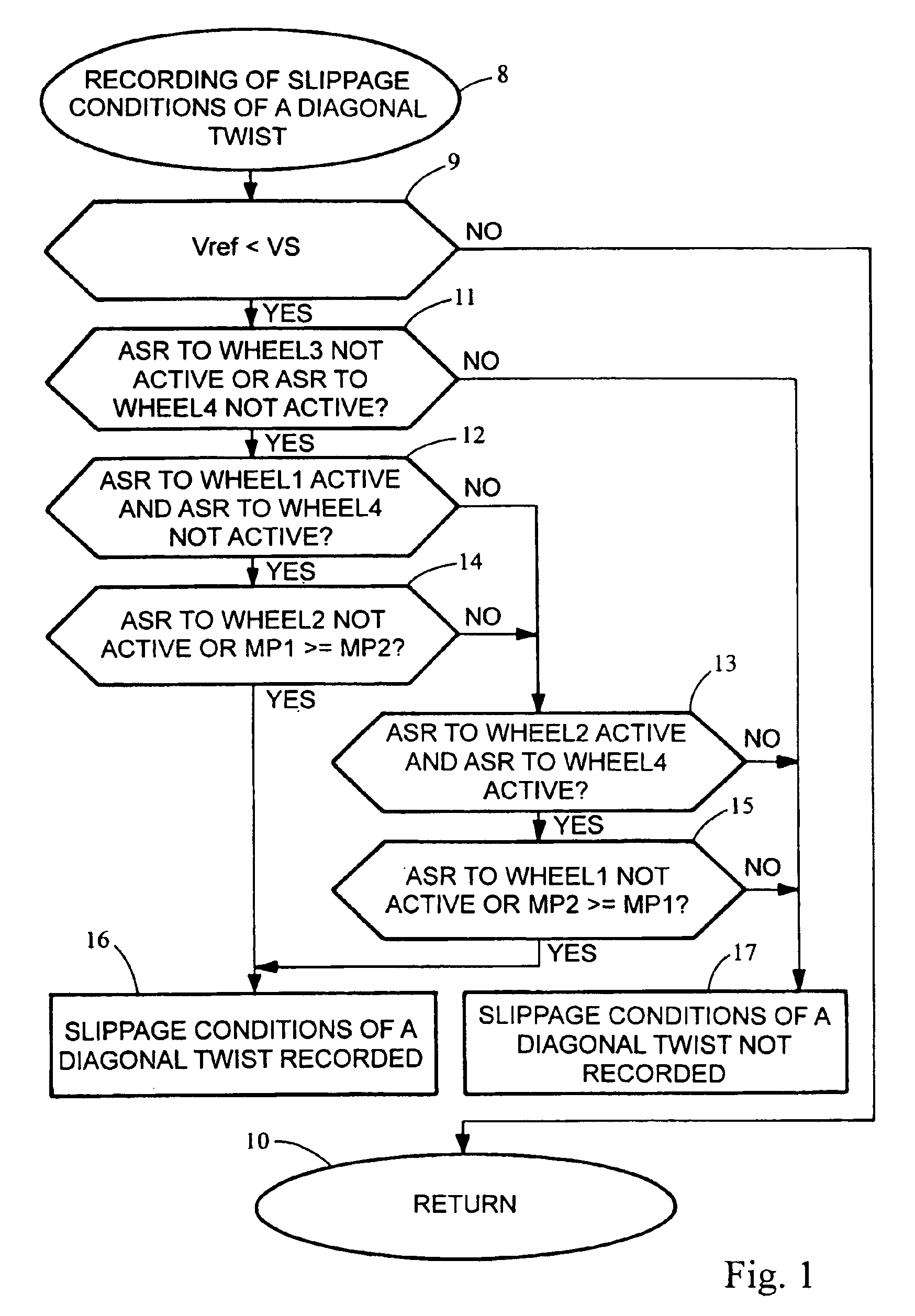
[0054]At the beginning after the Start (Step 8), In FIG. 1, a low vehicle speed or vehicle reference speed (Vref) lying below a speed threshold (VS) is required as a basic condition for detecting a slip condition of a diagonal axle twist. Since, in the case of a diagonal axle twist, the two wheels in contact with the ground usually do not overspeed, an estimated vehicle reference speed (Vref) corresponds quite well to the actual vehicle speed. In order to avoid unlearning the pattern when starting, preferably a Vref less than 3 to 15 km / h, e.g. less than about 6 km / h, is required. Contrary to the given concrete example of an embodiment (constant value), this speed threshold (VS) can also be a function of detection safety, because when there is a relatively high pressure level and relatively strong intervention of the traction-slip control, the vehicle speed, as a rule, will be relatively low, causing the above condition to be fulfilled.

[0055]In addition, the traction-slip control ma...


PUM


Abstract

The invention relates to a method for controlling a motor vehicle, in particular a traction-slip control system (TCS), wherein a diagonal axle twist is detected and evaluated as a regulating variable.

Description

FIELD OF THE INVENTION[0001]The present invention relates to a method for controlling a vehicle, in particular a traction-slip control system, as well as a method and circuit arrangement for detecting a diagonal axle twist in a vehicle with all-wheel drive.BACKGROUND OF THE INVENTION[0002]Vehicle control systems which reduce the wheel slip to a value appropriate for ensuring traction and driving stability by building up brake pressure on the overspeeding drive wheels and applying a stronger drive torque to the wheels with tire contact are known from the prior art. These systems are available both for two-wheel drive and all-wheel drive vehicles. These vehicle control systems are called traction-slip control systems (TCS), or also “Electronic Differential Lock”, “Automatic Stability Control,” and “Traction Control System”.[0003]Two designs have to be differentiated with respect to traction-slip control systems: traction-slip control and brake traction-slip control or brake traction-c...

Claims


Application Information

Patent Timeline
IPC IPC(8): G06F7/00B60T8/00B60T8/58F16H48/20
CPCB60T8/175B60T8/1769B60T2201/14
Inventor EHMER, NORBERTROLL, GEORGKIENLE, LOTHARHARTMANN, BERND-UWERITZ, STEFFENHALLER, FRANK
Owner CONTINENTAL TEVES AG & CO OHG
Learn More