Wrinkle reduction system using Bernoulli force rollers

a technology of bernoulli and rollers, applied in the field of media transport, can solve the problems of significant hysteresis, adversely affecting image quality, and introduction of significant moisture content to the receiver media, and achieve the effects of reducing fluttering in the receiver media web, reducing fluttering, and ensuring traction

Active Publication Date: 2015-07-14
EASTMAN KODAK CO
View PDF19 Cites 4 Cited by
  • Summary
  • Abstract
  • Description
  • Claims
  • Application Information

AI Technical Summary

Benefits of technology

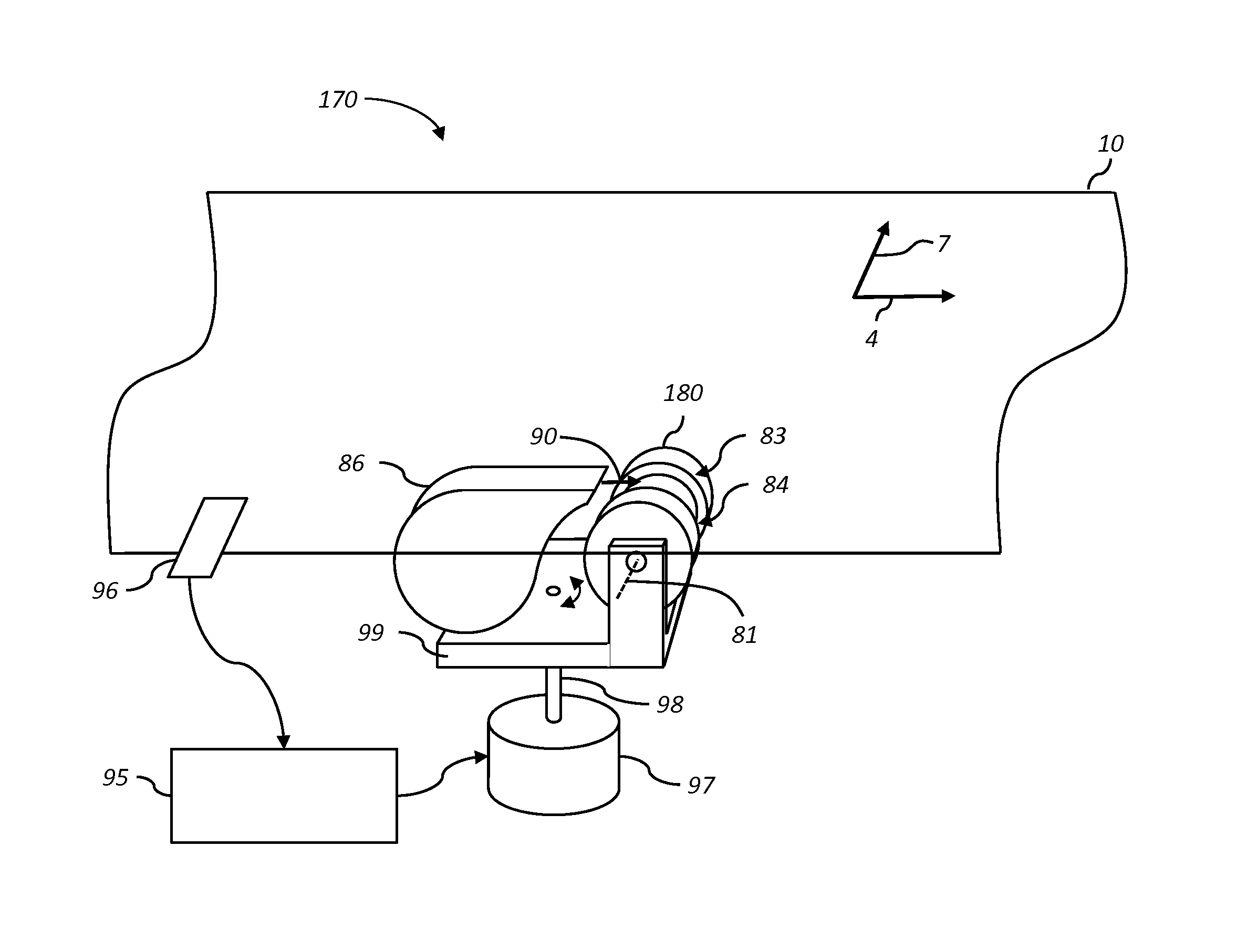
[0018]This invention has the advantage that adequate traction between the media and the media-guiding rollers can be produced to provide wrinkle reduction even when there is minimal wrap of the media around the media-guiding roller.
[0019]It has the additional advantage that in various embodiments the wrinkle-reduction system can also be used to steer the media.
[0020]It has the further advantage that it can reduce fluttering in receiver media webs that can result from insufficient traction between media-guiding rollers and the receiver media web in prior art systems.

Problems solved by technology

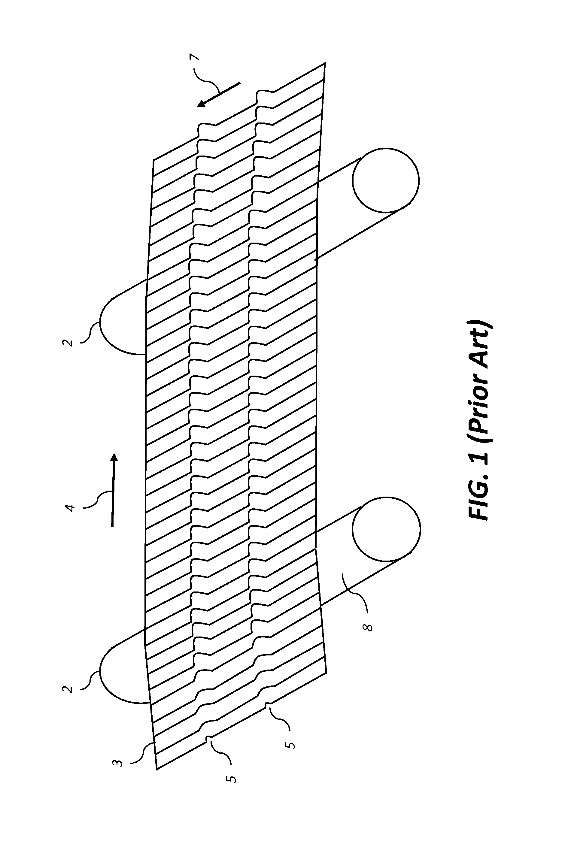
The jetting of liquid onto the receiver media introduces significant moisture content to the receiver media, particularly when the system is used to print multiple colors on a receiver media.
Due to the added moisture content, an absorbent receiver media expands and contracts in a non-isotropic manner, often with significant hysteresis.
The continual change of dimensional characteristics of the receiver media can adversely affect image quality.
Although drying is used to remove moisture from the receiver media, drying can also cause changes in the dimensional characteristics of the receiver media that can also adversely affect image quality.
Wrinkling of the receiver media 3 during the printing process can lead to permanent creases in the receiver media 3 which adversely affects image quality.

Method used


Image

  • Wrinkle reduction system using Bernoulli force rollers
  • Wrinkle reduction system using Bernoulli force rollers
  • Wrinkle reduction system using Bernoulli force rollers

Examples


Embodiment Construction

[0041]The present description will be directed in particular to elements forming part of, or cooperating more directly with, an apparatus in accordance with the present invention. It is to be understood that elements not specifically shown, labeled, or described can take various forms well known to those skilled in the art. In the following description and drawings, identical reference numerals have been used, where possible, to designate identical elements. It is to be understood that elements and components can be referred to in singular or plural form, as appropriate, without limiting the scope of the invention.

[0042]The invention is inclusive of combinations of the embodiments described herein. References to “a particular embodiment” and the like refer to features that are present in at least one embodiment of the invention. Separate references to “an embodiment” or “particular embodiments” or the like do not necessarily refer to the same embodiment or embodiments; however, such...


PUM


Abstract

A wrinkle-reduction system includes two media guiding rollers located in proximity to first and second edges of a media, each media guiding roller having a corresponding roller axis and having one or more grooves formed around its exterior surface. The media travels along a transport path past the media-guiding rollers with a first side of the media facing the exterior surface of the web-guiding rollers. Air sources provide an air flow into the grooves in the media-guiding rollers, the air flow being directed between the first side of the media and the exterior surface of the media-guiding rollers thereby producing a Bernoulli force to draw the media toward the media-guiding rollers. The first roller axis is not parallel to the second roller axis such that when the air sources are activated the media guiding rollers impart a lateral stretching force to the media in the cross-track direction.

Description

CROSS REFERENCE TO RELATED APPLICATIONS[0001]Reference is made to commonly assigned, co-pending U.S. patent application Ser. No. 14 / 016,427, entitled “Positive pressure web wrinkle reduction system,” by Kasiske Jr., et al.; to commonly assigned, co-pending U.S. patent application Ser. No. 14 / 190,146, entitled “Air shoe with roller providing lateral constraint,” by Cornell et al.; to commonly assigned, co-pending U.S. patent application Ser. No. 14 / 190,153, entitled “Air shoe with integrated roller,” by Cornell et al.; to commonly assigned, co-pending U.S. patent application Ser. No. 14 / 190,125, entitled “Media guiding system using Bernoulli force roller,” by Muir et al.; and to commonly assigned, U.S. patent application Ser. No. 14 / 190,137, now U.S. Pat. No. 8,936,243, entitled “Media diverter system using Bernoulli force rollers,” by Muir et al., each of which is incorporated herein by reference.FIELD OF THE INVENTION[0002]This invention pertains to the field of media transport and...

Claims


Application Information

Patent Timeline
Patent Type & Authority Patents(United States)
IPC IPC(8): B65H5/22B65H3/10B65H7/16B65H3/66B65H5/36
CPCB65H3/66B65H3/10B65H5/22B65H5/36B65H7/16B65H2406/12B65H23/26B65H9/166B65H23/022B65H23/038B65H2404/13161B65H2406/122B65H2801/15B65H2404/13171B65H9/105B65H2511/17B65H2515/84
Inventor MUIR, CHRISTOPHER M.CORNELL, DAVID JAMES
Owner EASTMAN KODAK CO
Why Eureka
Try Eureka