Butterfly valve for turbocharger systems

a turbocharger and valve body technology, applied in the direction of machines/engines, mechanical equipment, liquid fuel engines, etc., can solve the problems of lower hysteresis of the butterfly valve throughout the entire temperature range, and achieve reliable opening and closing, low leakage, and predictability of valve performance.

Active Publication Date: 2014-03-18
POWER PACKER NORTH AMERICA INC
View PDF24 Cites 17 Cited by
  • Summary
  • Abstract
  • Description
  • Claims
  • Application Information

AI Technical Summary

Benefits of technology

[0011]The shaft extends between the bores and laterally through the butterfly valve element. Two bushings are provided, one bushing being received in a different one of the bores, and each bushing extending from the bore inwardly into a counter bore in the butterfly valve element. The shaft extends in each of the bushings so as to journal the shaft relative to the housing. There is a first slip fit between the bushing and the counter bore and a second slip fit between the shaft and the bushing. These are made as small as possible, permitted by manufacturing tolerances, but preferably one of these slip fits is smaller (i.e. more accurate) than the other. Placing a tight control on the fit at only one of these junctures helps enable controlling leakage through the valve to a very low level, for example less than 1% using production machining processes, and also provides production consistency, predictability of the performance of the valve, and reliable opening and closing at the temperature and pressure extremes. This permits using a lower spring force to return the valve to its normal position, typically the closed position.
[0012]The invention results in a low leakage butterfly valve for turbocharger exhaust applications. One way it does this is by permitting the butterfly element to move sufficiently in the passageway when it is closing against the opposed lap seat surfaces so that the butterfly valve element can attain a flat or parallel orientation relative to the lap seat surfaces. Doing so creates a seal all of the way around the overlapping surfaces. It also does this by allowing the fit at the tighter of the two interfaces to be tighter than what would otherwise normally be permitted, thereby reducing the leak path through that interface. In addition, this construction, when coupled with appropriate material selections, results in a butterfly valve with lower hysteresis throughout the entire temperature range.

Problems solved by technology

In addition, this construction, when coupled with appropriate material selections, results in a butterfly valve with lower hysteresis throughout the entire temperature range.

Method used


Image

  • Butterfly valve for turbocharger systems
  • Butterfly valve for turbocharger systems
  • Butterfly valve for turbocharger systems

Examples


Embodiment Construction

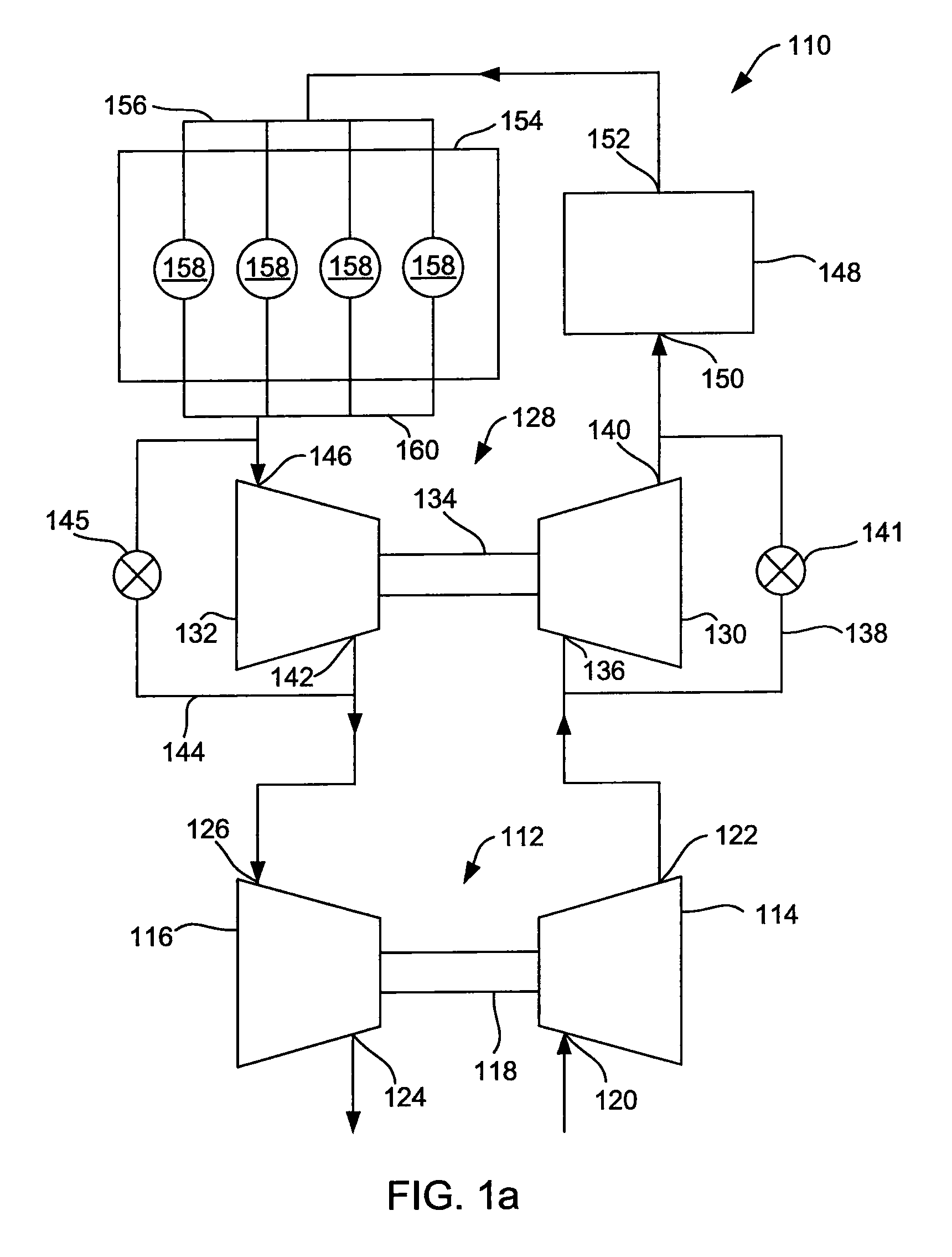
[0022]FIG. 1a shows a schematic representation of a series sequential turbocharger system 110. The system includes a low pressure turbocharger 112 having a low pressure compressor 114 and a low pressure turbine 116. A shaft 118 rotatably connects the low pressure compressor 114 and the low pressure turbine 116. The low pressure compressor 114 includes an inlet 120 that preferably fluidly communicates with the air filter (not shown) of the vehicle. The low pressure compressor 114 also includes an outlet 122 that fluidly communicates with other components of the system 110, as described below. The low pressure turbine 116 includes an outlet 124 that preferably fluidly communicates with the exhaust line (not shown) of the vehicle. The low pressure turbine 116 also includes an inlet 126 that fluidly communicates with other components of the system 110, as described below.

[0023]The system 110 includes a high pressure turbocharger 128 having a high pressure compressor 130 and a high press...


PUM


Abstract

A butterfly valve for a turbocharger system in which the leak path through the valve is controlled by keeping the clearance between either a shaft of the valve and two bushings small or the clearance between the bushings and the counter bores in the valve element small, and making the other clearance larger.

Description

CROSS-REFERENCE TO RELATED APPLICATIONS[0001]This application is a national phase application of International Application No. PCT / US2009 / 050076, filed Jul. 9, 2009, which claims the benefit of U.S. Provisional Patent Application No. 61 / 079,696 filed Jul. 10, 2008, the disclosure of which is hereby incorporated by reference in their entirety.STATEMENT CONCERNING FEDERALLY SPONSORED RESEARCH OR DEVELOPMENT[0002]Not applicable.FIELD OF THE INVENTION[0003]The present invention relates to valves for turbocharger systems, and in particular to such a valve that is a butterfly valve.BACKGROUND OF THE INVENTION[0004]Turbochargers have become popular for many different types of internal combustion engines, from large diesel engines to small gasoline engines. The purpose of the turbocharger in all of them is to provide a high pressure charge of a fluid or gas, typically air, to the combustion chamber of the engine. The turbocharger is typically driven by the exhaust of the engine, which is us...

Claims


Application Information

Patent Timeline
Patent Type & Authority Patents(United States)
IPC IPC(8): F02B33/44
CPCF02M25/0711F02D9/1015Y02T10/121F02M25/0709F02D9/1065F02B37/013F02B37/004F02D9/106F16K1/221F02B37/16F16K1/224F02M26/08
Inventor LILLY, DARYL, A.
Owner POWER PACKER NORTH AMERICA INC
Why Eureka
Try Eureka