Eureka AIR delivers breakthrough ideas for toughest innovation challenges, trusted by R&D personnel around the world.

Control System for a Stent Delivery System

Active Publication Date: 2012-01-26
COOK MEDICAL TECH LLC
View PDF16 Cites 12 Cited by
  • Summary
  • Abstract
  • Description
  • Claims
  • Application Information

AI Technical Summary

Benefits of technology

[0009]Accordingly, it is an object of the present invention to provide a device and a method having features that resolve or improve on one or more of the above-described drawbacks.
[0010]The foregoing object is obtained in one aspect of the present invention by providing a control system for a stent delivery system having a first shaft and a second shaft movable relative to the first shaft. The control system includes a housing having a chamber formed therein, a first drive at least partially positioned within the housing and operably connected to the first shaft of the delivery system and a second drive at least partially positioned within the housing and operably connected to the second shaft. The control system also includes a pressure controller operably connected to the housing and configured to change the pressure within the chamber. The first drive and the second drives are movable in response to the pressure change within the chamber and the movement of the second drive relative to the first drive causes the second shaft to move relative to the first shaft so as to expand or constrain a stent operably connected thereto.
[0011]In another aspect of the present invention, a stent delivery system is provided. The stent delivery system includes a first shaft, a second shaft movable relative to the first shaft and coaxially extending with the first shaft, a stent operably connected to the first shaft and

Problems solved by technology

Several problems may occur with the sheathed delivery device described above.
The sheath release delivery devices are difficult to reposition or remove and slow to operate.
For example, utilizing a conventional outer sheath / inner catheter delivery device may cause the physician to inadvertently use excessive force and pull back the outer sheath too far, thereby prematurely deploying the stent in an incorrect position within a body lumen.
At this step in the procedure, repositioning of the stent becomes difficult, if not impossible, because the stent has already radially self-expanded into the body lumen.
This type of release may cause difficulty in accurately placing the proximal portion of the stent because the distal end of the stent is positioned first while the proximal portion of the stent is still covered by the outer sheath.
An additional drawback occurs with the sheathed stent delivery system where direct visualization of the stent is required.
For example, in endoscopically placed stents, the sheath tends to prevent or obscure the location of the stent, making accurate placement of the stent more difficult.
Further potential drawbacks for the conventional sheathed stent delivery system involve the stent placement within the system prior to use within a patient.
Extended compression of the stent may lead to an alteration in the stent mechanical properties.
Conventional sheathed stent delivery devices also require a high force to overcome the friction between the stent and the sheath that may also be a problem for proper stent placement within the patient.
The sheathed stent delivery device also requires more space within an endoscope compared to a sheathless device and also adds additional expense to the delivery system.

Method used


Image

  • Control System for a Stent Delivery System
  • Control System for a Stent Delivery System
  • Control System for a Stent Delivery System

Examples


Embodiment Construction

[0023]The invention is described with reference to the drawings in which like elements are referred to by like numerals. The relationship and functioning of the various elements of this invention are better understood by the following detailed description. However, the embodiments of this invention are not limited to the embodiments illustrated in the drawings. It should be understood that the drawings are not to scale, and in certain instances details have been omitted which are not necessary for an understanding of the present invention, such as conventional fabrication and assembly.

[0024]As used in the specification, the terms proximal and distal should be understood as being in the terms of a physician delivering the stent to a patient. Hence the term “distal” means the portion of the delivery system that is farthest from the physician and the term “proximal” means the portion of the delivery system that is nearest to the physician.

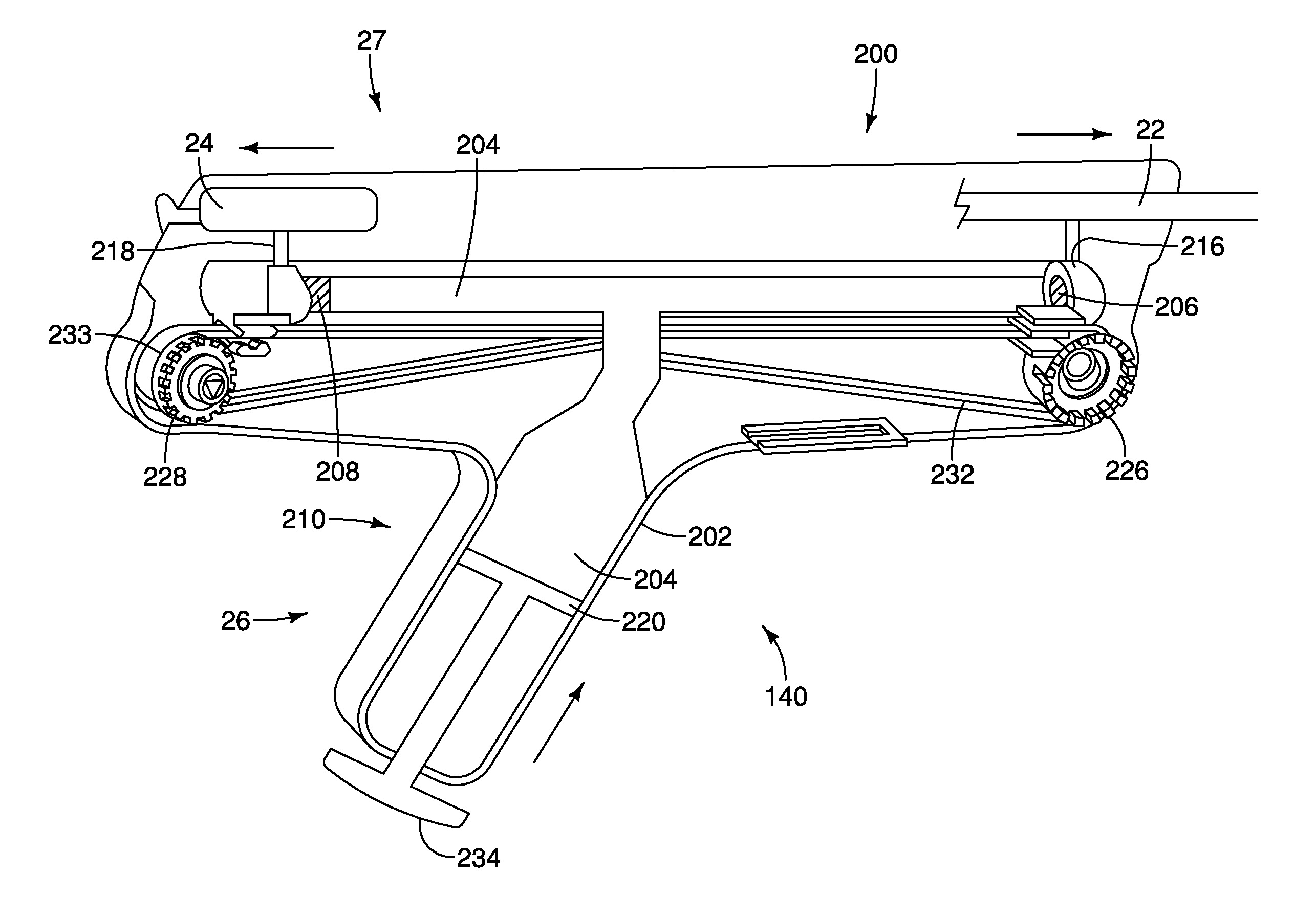
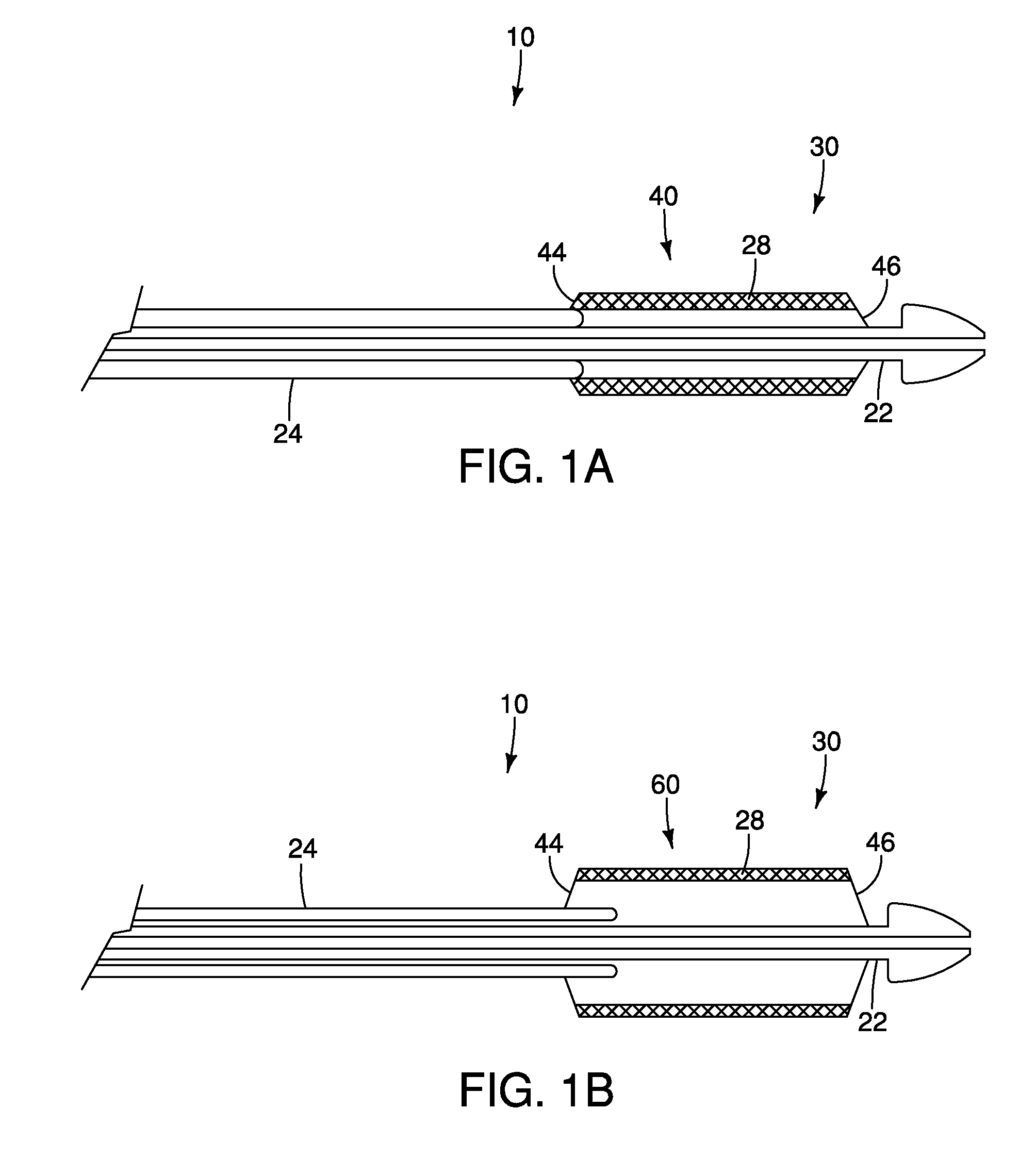
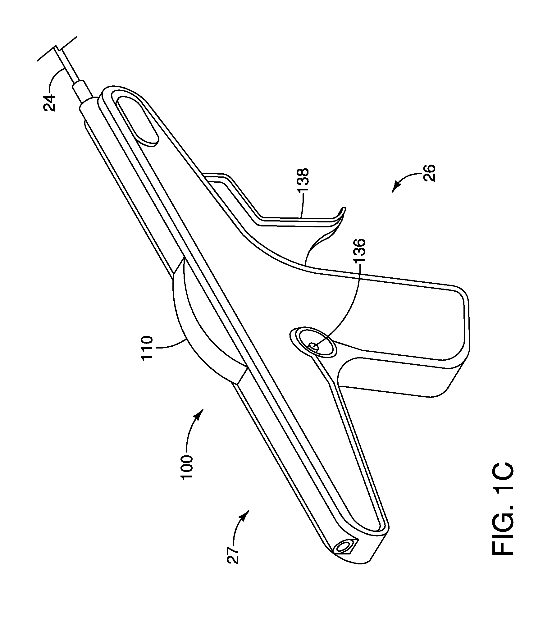
[0025]FIGS. 1A and 1B illustrate a distal porti...


PUM


Abstract

A control system for controlling movement of a stent delivery system, a stent delivery system and a method for controlling movement of a stent delivery system are provided. The control system includes a housing having a chamber formed therein, a first drive at least partially positioned within the housing and operably connected to the first shaft of the delivery system and a second drive at least partially positioned within the housing and operably connected to the second shaft. The control system also includes a pressure controller operably connected to the housing and configured to change the pressure within the chamber. The first drive and the second drives are movable in response to the pressure change within the chamber and movement of the second drive relative to the first drive causes the second shaft to move relative to the first shaft to expand or constrain a stent operably connected thereto.

Description

RELATED APPLICATIONS[0001]This application claims the benefit of U.S. Provisional Application No. 61 / 366,228, filed Jul. 21, 2010, which is incorporated by reference herein in its entirety.TECHNICAL FIELD[0002]This invention relates to a medical device and, in particular to a control system for a device for delivering and deploying a stent and a method of controlling the stent delivery system.BACKGROUND[0003]A self-expanding stent is typically introduced into the body using a delivery device that includes an outer sheath coaxially disposed and slidable over an inner catheter. The stent is disposed at the distal end of the device between the inner catheter and the outer sheath and held in a compressed position by the outer sheath. The inner catheter and the outer sheath move coaxially with respect to each other. The stent may be deployed by proximally pulling back the outer sheath relative to the inner catheter until the stent is exposed. The self-expanding stent expands from the ste...

Claims


Application Information

Patent Timeline
IPC IPC(8): A61F2/84
CPCA61F2/95A61F2/966A61M2025/0175A61F2002/9517A61M2025/0006A61F2002/9511A61F2/9517
Inventor COSTELLO, KIERAN
Owner COOK MEDICAL TECH LLC
Why Eureka
Eureka Blog
Learn More