Return Fan Control System and Method

a control system and fan technology, applied in the direction of instruments, heating types, static/dynamic balance measurement, etc., can solve the problems of not providing direct control of building pressure, difficult, if not impossible practically, and difficulty in maintaining a 5:1 response tim

a control system and fan technology, applied in the direction of instruments, heating types, static/dynamic balance measurement, etc., can solve the problems of not providing direct control of building pressure, difficult, if not impossible practically, and difficulty in maintaining a 5:1 response tim

US20100057258A1Active Publication Date: 2010-03-04TRANE INT INC

Image

  • Return Fan Control System and Method
  • Return Fan Control System and Method
  • Return Fan Control System and Method

Examples


Embodiment Construction

[0029]As a preface to the detailed description, as used in this specification and the appended claims, the singular forms β€œa,β€β€œan,” and β€œthe” also include plural referents, unless the context clearly dictates otherwise.

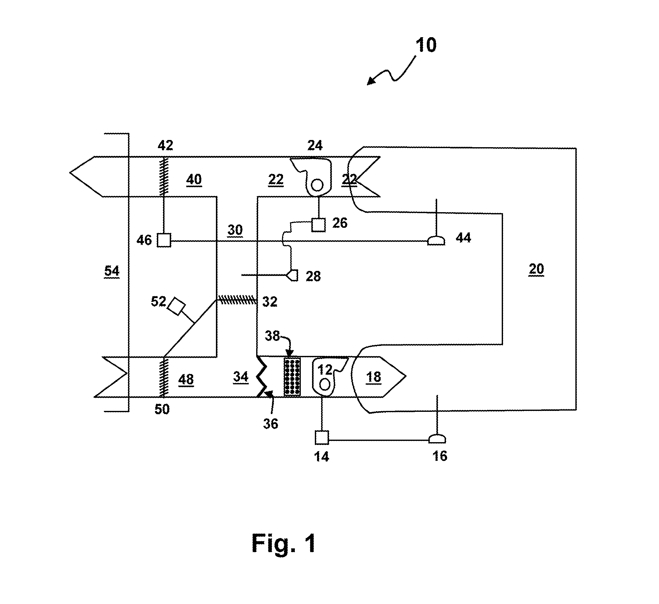
[0030]Referring to FIG. 1, a heating, ventilating, and air conditioning (HVAC) system 10 for heating and / or cooling building spaces is depicted, along with basic components discussed further below. The HVAC system 10 may include many other conventional features not depicted for simplicity of the drawings. In addition, values or ranges of values for HVAC system 10 parameters, subsystems thereof, are provided for illustrative purposes. It should be understood that other values or ranges of values for system parameters may be used depending on system needs and remain within the scope and spirit of embodiments of the present invention.

[0031]The HVAC system 10 is directed to systems in the range of about 20 to 200 tons or larger. Embodiments of the present invention apply ...


PUM


Abstract

A return fan control system for an HVAC system comprises a supply fan control loop, a return fan control loop and a building pressure control system. The supply fan control loop comprises a duct pressure controller arranged to control a supply fan to a duct pressure setpoint. The return plenum pressure control loop comprises a return plenum pressure controller arranged to automatically control a return fan to a return plenum pressure setpoint determined by a setpoint reset function. The building pressure control system is operable to control a building pressure. The building pressure control system may comprise a building pressure control loop and an outside air control loop cooperatively arranged to control an exhaust damper in response to an outside air intake.

Description

CROSS-REFERENCE TO RELATED APPLICATIONS[0001]Not applicable presently.FEDERALLY SPONSORED RESEARCH OR DEVELOPMENT[0002]None.BACKGROUND OF THE INVENTION[0003]This invention relates generally to the field of heating, ventilating, and air conditioning (HVAC) systems and, particularly, to air handling products with an airside economizer, a return fan and a building pressure control requirement. Embodiments of the present invention apply to controls for air handling units with a constant volume or variable volume supply fan, a variable volume return fan, and a central exhaust that are used in commercial rooftop products or other HVAC products with similar design characteristics.[0004]Generally, HVAC systems are used to heat and / or cool building spaces. Such building spaces include single story and multi-story schools, office buildings, and manufacturing facilities, for example. These systems may be unitary or built-up systems, and may be used to condition the air in multiple zones or bui...

Claims


Application Information

Patent Timeline
04 Mar 2010
Publication
US20100057258A1
IPC
G05D16/20; G05D23/00; F24F11/04; G05B13/00
CPC
F24F11/0001; F24F2011/0002; F24F2011/0006; F24F11/022; G05D16/2066; G05D23/19; F24F2011/0042; F24F2110/40
Inventors
CLANIN, THOMAS J.