Methods and apparatus for maintaining a pressure within an environmentally controlled chamber

Inactive Publication Date: 2005-07-12
APPLIED MATERIALS INC
View PDF14 Cites 51 Cited by
  • Summary
  • Abstract
  • Description
  • Claims
  • Application Information

AI Technical Summary

Benefits of technology

[0015]Other features and advantages of the present invention will become more fully apparent

Problems solved by technology

For example, the mainframe controller 110's empirical calculation of both a flow rate for the mass flow controller 112 and a throttle valve position for the throttle valve 116 based on a measured pressure within the transfer chamber 102 is a complex calculation that (1) is not highly accurate (e.g., as the method by which a mass flow controller measures mass flow is prone to error unless repe

Method used


Image

  • Methods and apparatus for maintaining a pressure within an environmentally controlled chamber
  • Methods and apparatus for maintaining a pressure within an environmentally controlled chamber
  • Methods and apparatus for maintaining a pressure within an environmentally controlled chamber

Examples


Embodiment Construction

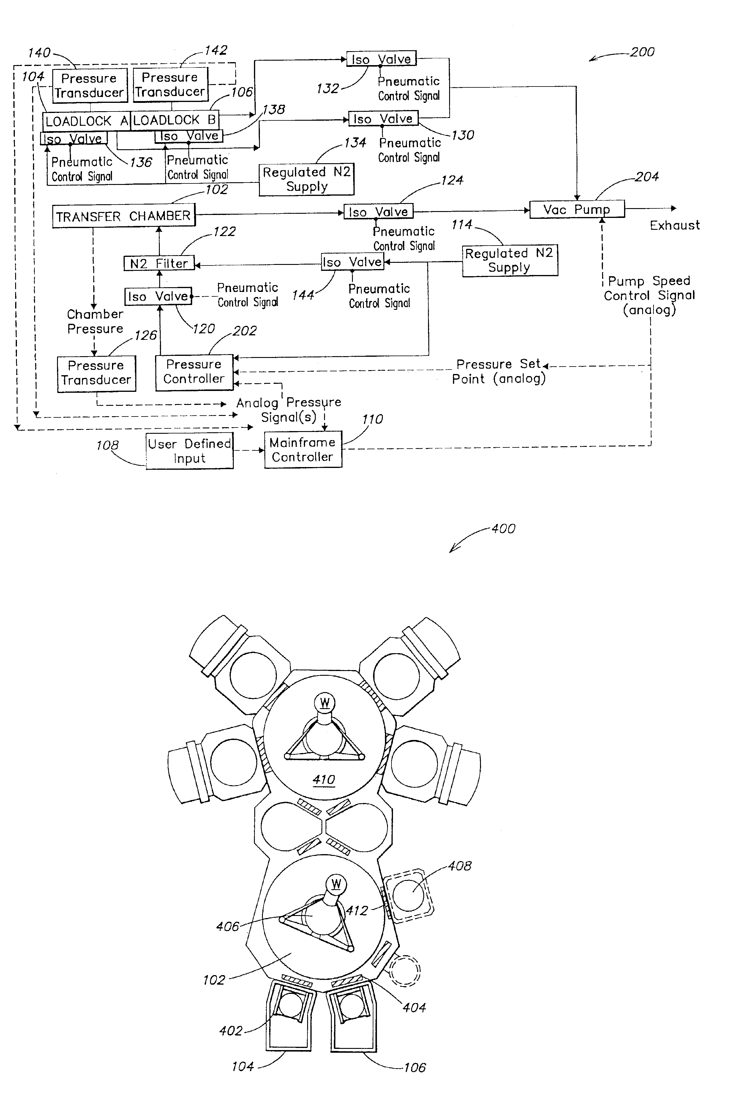
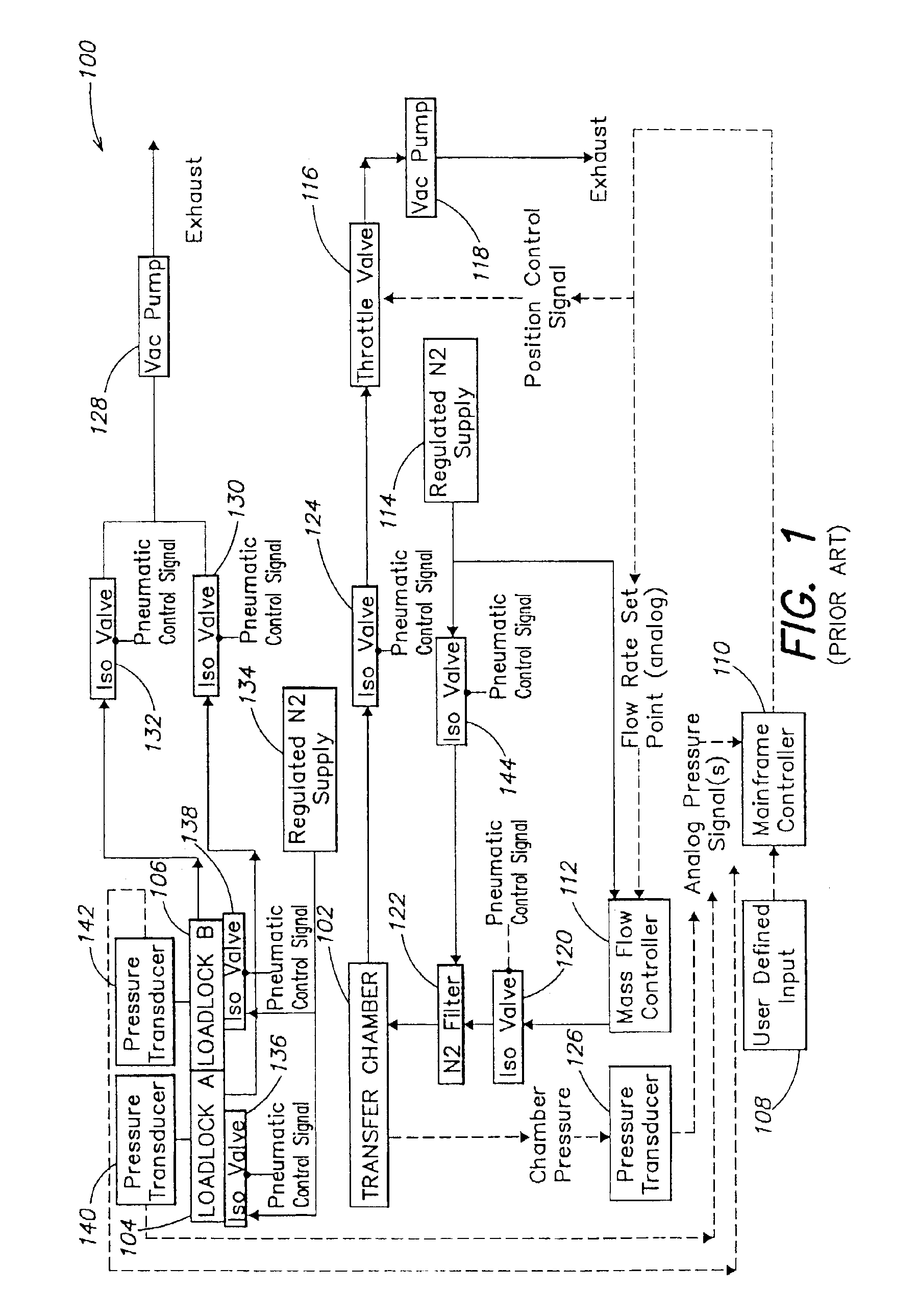
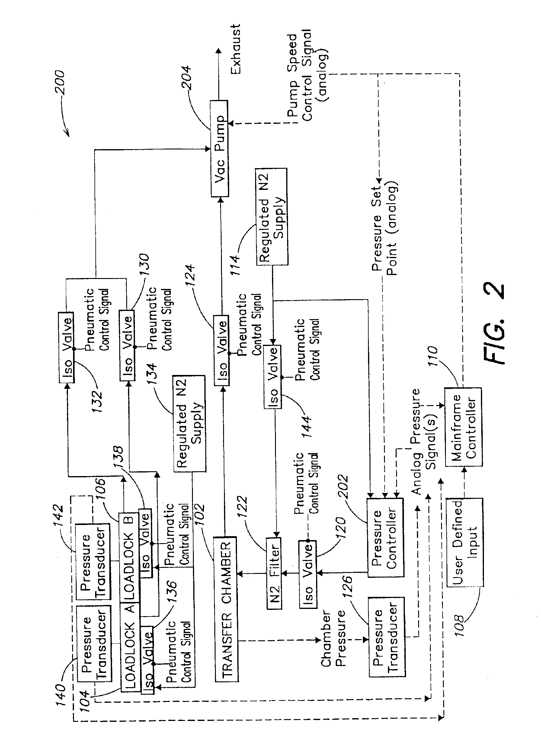
[0020]To address the needs of the prior art an inventive system is provided for maintaining a pressure within a vacuum chamber (such as a transfer chamber, a processing chamber or the like). Specifically, FIG. 2 is a block diagram of an exemplary inventive system 200 for maintaining a pressure within a transfer chamber of a semiconductor device manufacturing tool (e.g., the Endura™ (shown in FIG. 4) or the Centura™ (not shown), both manufactured by Applied Materials, Inc.). While the present invention is described below with reference to a transfer chamber of a semiconductor device manufacturing tool, it will be understood that the invention may be employed with any environmentally controlled chamber, whether the chamber is operated above, at or below atmospheric pressure.

[0021]For convenience, only the differences between the conventional system 100 of FIG. 1 and the inventive system 200 of FIG. 2 are described herein, and like reference numbers are employed for components that per...


PUM

PropertyMeasurementUnit
Pressureaaaaaaaaaa
Flow rateaaaaaaaaaa
Speedaaaaaaaaaa

Abstract

In a first aspect, a system includes (1) a chamber; (2) a variable speed vacuum pump coupled to the chamber; and (3) a pressure controller coupled to the chamber. The pressure controller compares a set point pressure with a pressure measurement for the chamber and adjusts a flow of gas through the pressure controller based on a difference between the pressure measurement and the set point pressure. The system includes a pressure measurement device coupled to the chamber and to the pressure controller, and a main controller coupled to the variable speed vacuum pump, the pressure controller and the pressure measurement device. The pressure measurement device measures a pressure within the chamber and provides a pressure measurement to the pressure controller and the main controller. The main controller (1) adjusts a speed of the variable speed vacuum pump; and (2) provides the set point pressure to the pressure controller.

Description

[0001]This patent application claims priority from U.S. Provisional Patent Application Ser. No. 60 / 211,402, filed Jun. 14, 2000, which is hereby incorporated by reference herein in its entirety.FIELD OF THE INVENTION[0002]The present invention relates to vacuum technology and more particularly to methods and apparatus for maintaining a pressure within an environmentally controlled chamber such as a vacuum chamber.BACKGROUND OF THE INVENTION[0003]FIG. 1 is a block diagram of a conventional system 100 for maintaining a pressure within a transfer chamber 102 of a semiconductor device manufacturing tool (e.g., the Endura™ (shown in FIG. 4) or the Centura™, both manufactured by Applied Materials, Inc.). The transfer chamber 102 is shown coupled to a first load lock 104 and to a second load lock 106. The load locks 104, 106 are adapted to transfer semiconductor wafers to and / or from the transfer chamber 102 as is well known in the art.[0004]With reference to FIG. 1, to employ the conventi...

Claims


Application Information

Patent Timeline
IPC IPC(8): G05D16/20H01L21/00B01J3/00B01J3/02
CPCG05D16/2066H01L21/67253G05D16/20
Inventor PFEIFFER, KENNETHVERDICT, GREGORY S.
Owner APPLIED MATERIALS INC
Why Eureka
Try Eureka