Devices, systems, and methods for cutting and removing occlusive material from a body lumen

a technology of occlusive material and body lumen, which is applied in the field of treatment of occlusive body lumen, can solve the problems of unacceptably high restnosis rate, barotrauma to the vessel, and the embolization of a downstream vessel, and achieve the effect of safe, efficient and controlled shaving or grinding of material

Inactive Publication Date: 2011-02-17
ATHEROMED
View PDF99 Cites 150 Cited by
  • Summary
  • Abstract
  • Description
  • Claims
  • Application Information

AI Technical Summary

Problems solved by technology

Often plaque is friable and may dislodge naturally or during an endovascular procedure, leading to embolization of a downstream vessel.
Balloon angioplasty is known to cause barotrauma to the vessel from the high pressures required to compress the plaque.
This trauma leads to an unacceptably high rate of restenosis.
Furthermore, this procedure may not be efficient for treatment of elastic-type plaque tissue, where such tissue can spring back to occlude the lumen.
On their own, stents fail to perform well in the peripheral vasculature for a variety of reasons.
A stent with the necessary structural integrity to supply sufficient radial force to reopen the artery often does not perform well in the harsh mechanical environment of the peripheral vasculature.
Such an environment may lead to stent failure (strut cracking, stent crushing, etc.) that eventually compromises the ability of the stent to maintain lumen diameter over the long-term.
On the other hand, a stent that is able to withstand the harsh mechanical aspects of the periphery often will not supply enough radial force to open the vessel satisfactorily.

Method used


Image

  • Devices, systems, and methods for cutting and removing occlusive material from a body lumen
  • Devices, systems, and methods for cutting and removing occlusive material from a body lumen
  • Devices, systems, and methods for cutting and removing occlusive material from a body lumen

Examples


Embodiment Construction

[0035]Although the disclosure hereof is detailed and exact to enable those skilled in the art to practice the invention, the physical embodiments herein disclosed merely exemplify the invention, which may be embodied in other specific structure. While the preferred embodiment has been described, the details may be changed without departing from the invention, which is defined by the claims.

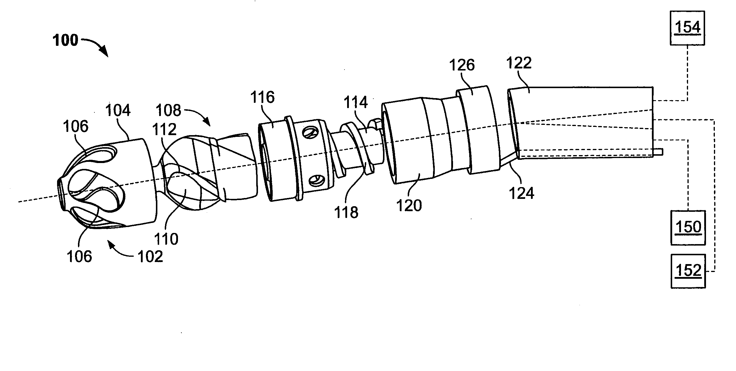
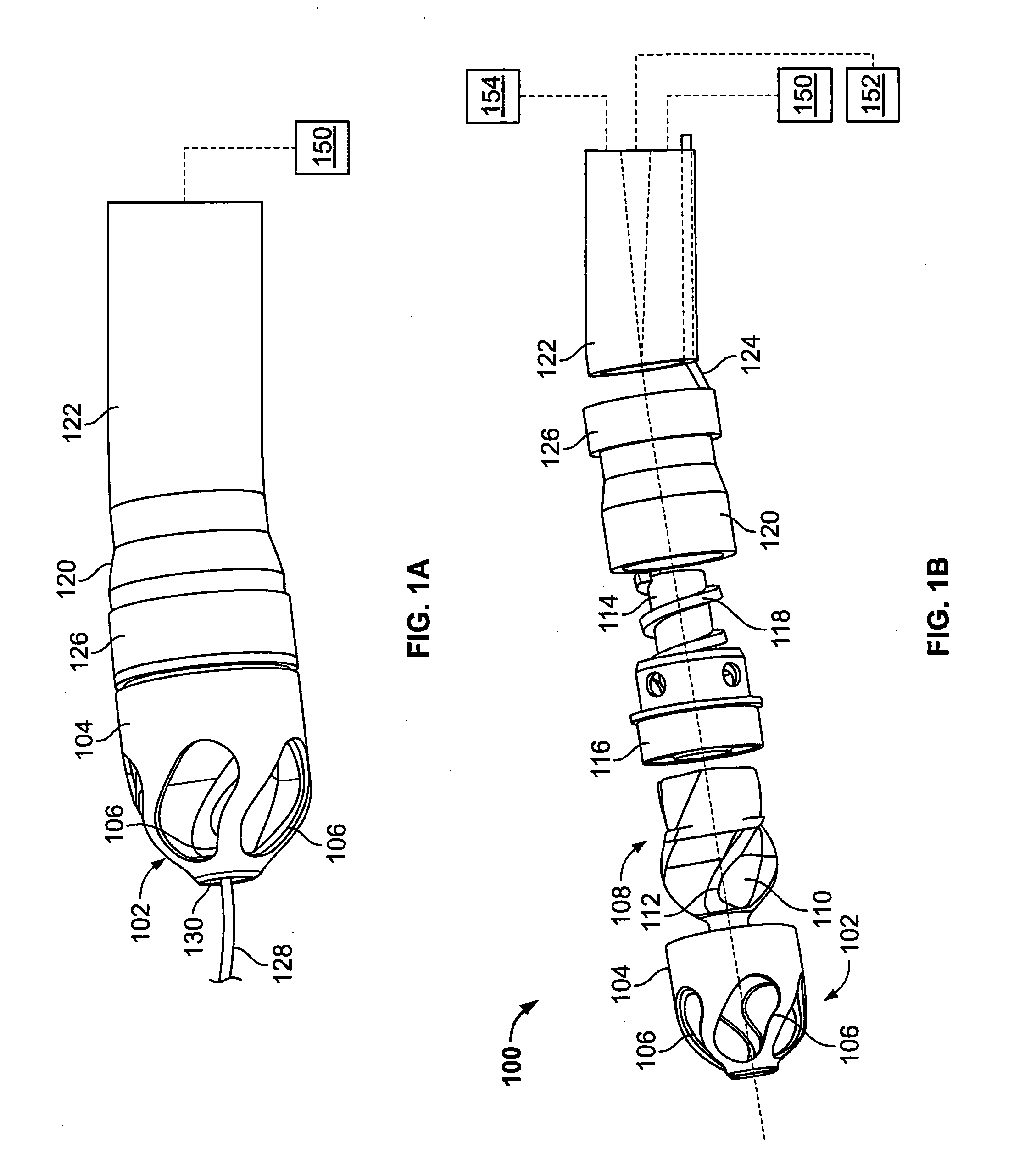
[0036]FIG. 1A illustrates an exemplary variation of a device 100 according to the present invention. As shown the device 100 includes a cutter assembly 102 affixed to a catheter body 120. As shown, the catheter body may be optionally located within an outer sheath 122.

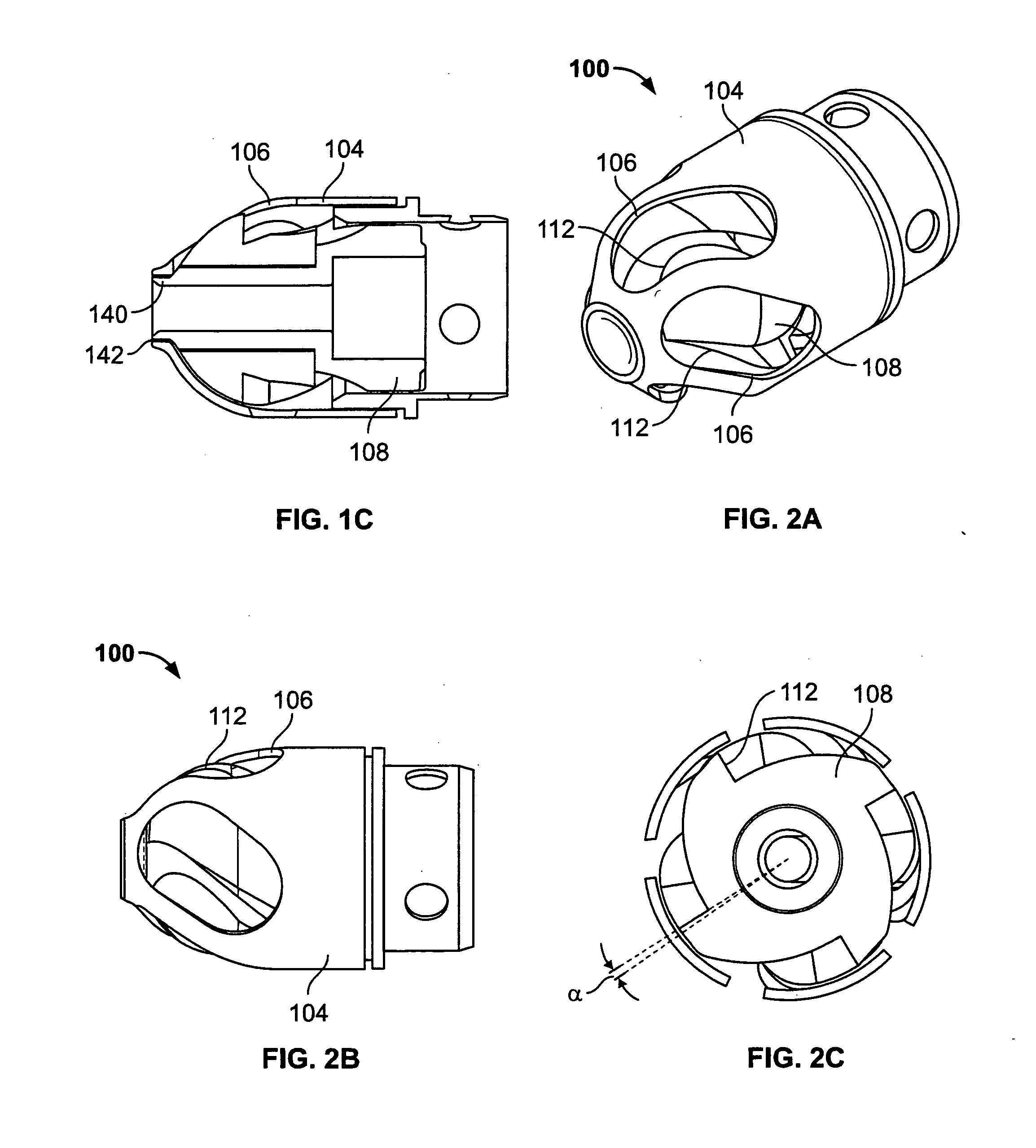
[0037]FIG. 1B illustrates an exploded view of the device 100 of FIG. 1A. As shown, the cutter assembly 102 includes a housing 104 with a plurality of openings 106. A cutter 108 is located within the housing 104. The cutter 108 includes one or more flutes 110 each of which includes an edge or cutting surface 112. The cutter is coupled...


PUM


Abstract

A vascular device is provided having a catheter body and a rotatable cutter assembly located at the distal end of the catheter body. The cutter assembly has at least one helical cutting surface within a housing that is coupled by a torque shaft to a drive mechanism. A conveyor mechanism helically wound about the torque shaft conveys occlusive material conveyed into the housing by the helical cutting blade further proximally along the catheter body for discharge without supplement of a vacuum pump. The catheter body is manipulated to insert the distal end of the catheter body within a body lumen and advance the distal end of the catheter body toward the occlusive material. The drive mechanism is operated to rotate the helical cutting surface to cut and convey the occlusive material from the body lumen proximally into the housing and to convey the occlusive material conveyed into the housing by the helical cutting surface further proximally along the catheter body by the conveyor mechanism for discharge without supplement of a vacuum pump. The distal end of the catheter body is deflected and rotated to sweep the cutter assembly in an arc about the center axis of the catheter body to cut occlusive material in a region larger than the outside diameter of the cutter assembly.

Description

RELATED APPLICATION[0001]This application is a continuation of co-pending U.S. application Ser. No. 11 / 567,715, filed 6 Dec. 2006 and entitled “Atherectomy Devices and Methods,” which is a continuation of co-pending U.S. application Ser. No. 11 / 551,191, filed 19 Oct. 2006 and entitled “Atherectomy Devices and Methods,” which claims the benefit of U.S. Provisional Application Ser. No. 60 / 806,417 entitled “Atherectomy Device” filed Jun. 30, 2006 and U.S. Provisional Application Ser. No. 60 / 820,475 entitled “Atherectomy Device” filed Jul. 26, 2006, the entirety of each of which are hereby incorporated reference.FIELD OF THE INVENTION[0002]The invention generally relate to treatment of occluded body lumens. In particular, the present devices and method relate to removal of the occluding material from the blood vessels as well as other body lumens.BACKGROUND OF THE INVENTION[0003]Atherosclerosis is a progressive disease. In this disease, lesions of the arteries are formed by accumulation...

Claims


Application Information

Patent Timeline
Patent Type & Authority Applications(United States)
IPC IPC(8): A61B17/22
CPCA61B2017/22041A61B2017/22038A61B2017/003A61B17/320758A61B2090/3735A61B2090/3784A61B2017/00318A61B2017/320775A61M25/0152A61M25/0155A61B2017/00331A61B2017/00685A61B2017/22039A61B2017/22044A61B2017/22068A61B2017/22094A61B17/320783A61B2017/320716A61B2017/320741A61B2017/22042A61B2017/22079A61B2017/320733A61B17/22
Inventor TO, JOHNDANEK, CHRISTOPHER JAMES
Owner ATHEROMED
Why Eureka
Try Eureka