Linear abrasive brush member, method for preparing linear abrasive brush member, and abrasive brush

Inactive Publication Date: 2012-02-02
3M INNOVATIVE PROPERTIES CO
View PDF23 Cites 2 Cited by
  • Summary
  • Abstract
  • Description
  • Claims
  • Application Information

AI Technical Summary

Benefits of technology

[0013]It is desired to provide a linear abrasive brush member which is hardly broken in production or use, in which the substrate part is excellent in deformability, and an abrasive brush is easily provided in a variety of sizes and shapes using the linear abrasive brush member.
[0028]The substrate part of the linear abrasive brush member of the present invention is excellent in deformability. It therefore is possible to easily provide a wheel-shaped abrasive brush or a disk-shaped abrasive brush by bending the brush member along a properly shaped supporting member. Moreover, since the brush member is linear, its length has a high degree of freedom, and it is possible to change the external shape or dimensions of an abrasive brush freely. The substrate part has a core material which affords sufficient strength, and the linear abrasive brush member is hardly broken as production or use. In addition, the filament parts are molded and not oriented, and are hardly broken and excellent in abrasion ability.

Problems solved by technology

However, there are the following problems in conventional linear abrasive brush members.
Since fibers are fastened with a metal sleeve by caulking, filaments tend to break due to application of load on the caulked part.
The production requires complicated works and a large cost because the number of constituent parts is large.
Abrasion ability is weak because filaments are thin and cylindrical.
Therefore, abrasive brushes using the abrasive brush members integrally molded from a resin require much labor and costs for changing their external shapes or dimensions.
The material of the abrasive brush member disclosed in patent document 2 is not a thermoplastic elastomer and thus is insufficient in elasticity.
Therefore, the filament parts are easily broken and the substrate part is inferior in deformability.
The substrate part is insufficient in strength, and is inferior in safety for using high-speed rotational abrasive brushes.

Method used


Image

  • Linear abrasive brush member, method for preparing linear abrasive brush member, and abrasive brush
  • Linear abrasive brush member, method for preparing linear abrasive brush member, and abrasive brush
  • Linear abrasive brush member, method for preparing linear abrasive brush member, and abrasive brush

Examples


example

[0098]A resin composition was prepared by mixing 100 parts of thermoplastic elastomer (“HYTREL™ 5527” produced by du Pont Toray Co., Ltd.), 10 parts of an additive (“SILICONE BATCH™ BY 27010” produced by Dow Corning Toray Co., Ltd.). An injection molding method was conducted with the resin composition and cotton thread of 0.8 mm thickness as a core material to obtain a linear abrasive brush member in which each molded body unit from a metal mold is connected each other.

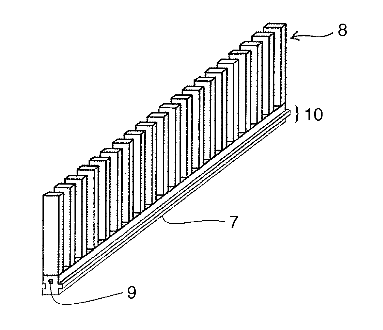
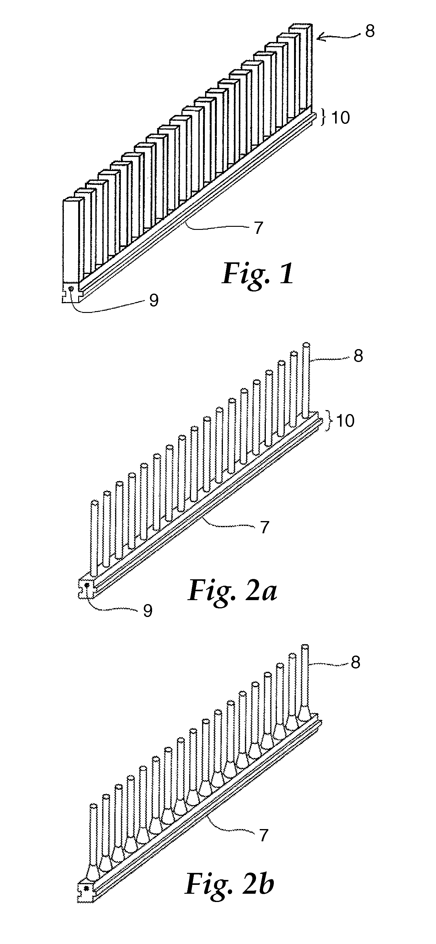
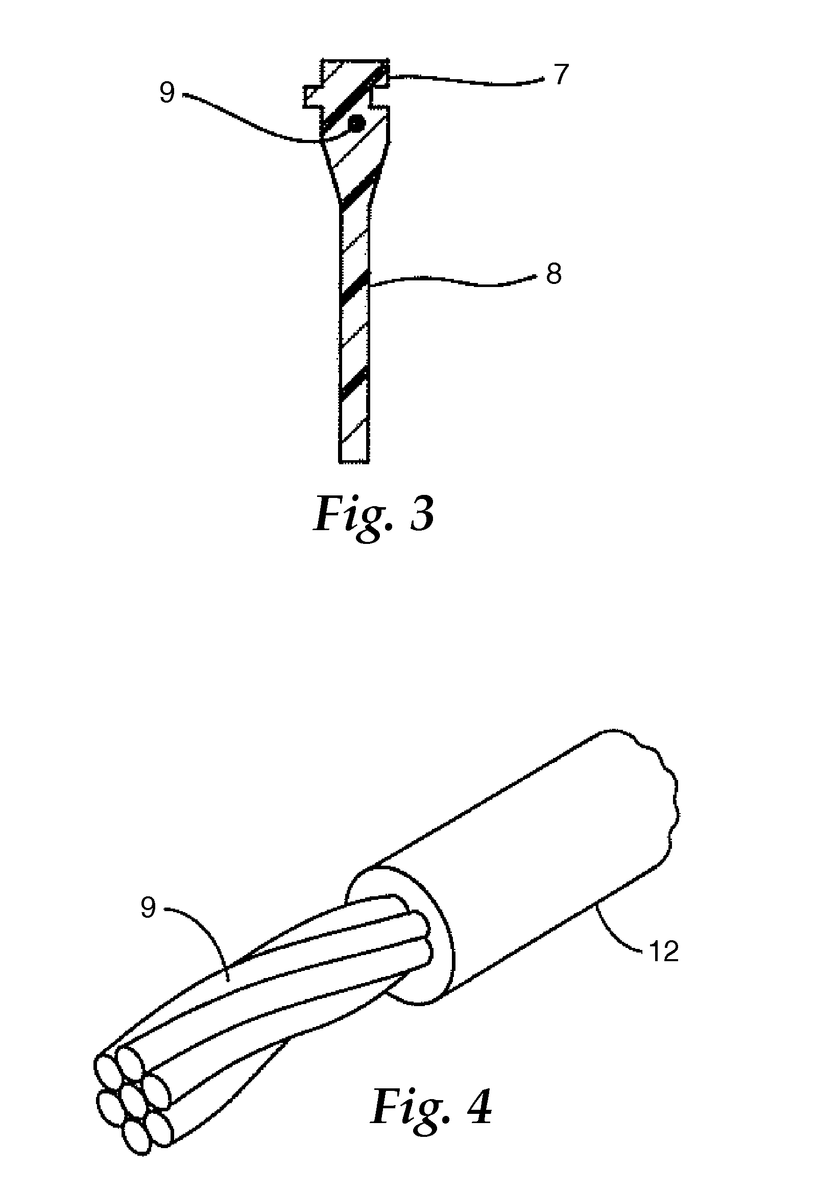
[0099]FIG. 19 is a partially enlarged perspective view of the linear abrasive brush member obtained. The section of the substrate part was about a rectangle, which had a length a of 5 mm and a width b of 3 mm. On one side surface of the substrate part, a groove with 1 mm-width and 1 mm-depth is formed along the longitudinal direction as a mating structure. A mesa that fits to the groove is formed on the other side surface. The external shape of each filament part is nearly an oblong having thickness. The thickness c i...


PUM

PropertyMeasurementUnit
Fractionaaaaaaaaaa
Breaking strengthaaaaaaaaaa

Abstract

To provide a linear abrasive brush member, in which filament parts are hardly broken, a substrate part is excellent in deformability, and also, abrasion ability is excellent. A linear abrasive brush member comprising: an embedded core material (9); a rod-shaped substrate part (7) having opposite long-narrow upper and bottom faces; and a plurality of filament parts (8) present on the upper surface along the longitudinal direction; and the substrate part and the filament parts being integrally molded from a resin composition.

Description

TECHNICAL FIELD[0001]The present invention relates to linear abrasive brush members, methods for preparing thereof, and abrasive brushes composed of the members.BACKGROUND[0002]The term “abrasive brush” refers to an abrasive material which comprises a main body of the brush and a large number of filaments extending from the main body and exerts an abrasive function through rubbing a workpiece with the filaments. The “filament” refers to a fibrous member, which has a small sectional area, and is long and easy to bend.[0003]An abrasive brush may comprise a plurality of members. For example, an abrasive brush may be constituted by fastening a member composed of bundled filaments to a main body having a handle, a mounting part, etc. This is because making a module of filaments apart from a main body will make it easy to vary the shape of an abrasive brush depending on the use thereof. In this specification, a component of an abrasive brush in which filaments are bundled is referred to a...

Claims


Application Information

Patent Timeline
IPC IPC(8): B24D3/00B24D13/02B24D18/00
CPCA46B3/02A46B3/16A46B3/18A46B13/005A46B13/006A46B13/008B29L2031/7654B24D13/145B24D18/0009B29C45/0003B29C45/0013B29C45/2626B24D13/10Y10T428/249942
Inventor NAGAFUCHI, NAOHIRO
Owner 3M INNOVATIVE PROPERTIES CO
Why Eureka
Try Eureka