System and method for reducing false alarms associated with vital-signs monitoring

a vital sign and monitor technology, applied in the field of physiological monitoring, can solve the problems of difficult continuous monitoring, intrusive monitoring of certain vital signs, and relatively complicated equipment to achieve, so as to reduce or eliminate false alarms, avoid unnecessary trips or other actions, and reduce false alarms

Active Publication Date: 2012-02-02
CAREFUSION 303 INC
View PDF21 Cites 89 Cited by
  • Summary
  • Abstract
  • Description
  • Claims
  • Application Information

AI Technical Summary

Benefits of technology

[0013]In addition, certain embodiments of the patient monitoring system disclosed herein can send alarm notifications to a hospital system if the vital-sign readings satisfy an alarm condition. It is desirable to reduce or eliminate false positives in the alarm notifications so as to avoid unnecessary trips or other actions of a healthcare provider that such false positives can cause.
[0014]In one aspect of the present disclosure, a method of reducing false alarms associated with a vital-sign monitor is disclosed. The method can comprise generating one or more data samples of a vital sign of a patient at a first sampling rate in a normal mode of operation. The method can further comprise determining whether the one or more data samples satisfies an alert condition. The method can further comprise entering an alert mode of operation if the alert condition is satisfied. The method can further comprise generating one or more additional data samples of the vital sign at a second sampling rate higher than the first sampling rate in the alert mode.

Problems solved by technology

A typical interval is 4 hours, which leads to the undesirable requirement for a nurse to awaken a patient in the middle of the night to take vital sign measurements.
Measuring certain vital signs is normally intrusive at best and difficult to do on a continuous basis.
Measurement of respiration is easy for a nurse to do, but relatively complicated for equipment to achieve.

Method used


Image

  • System and method for reducing false alarms associated with vital-signs monitoring
  • System and method for reducing false alarms associated with vital-signs monitoring
  • System and method for reducing false alarms associated with vital-signs monitoring

Examples


Embodiment Construction

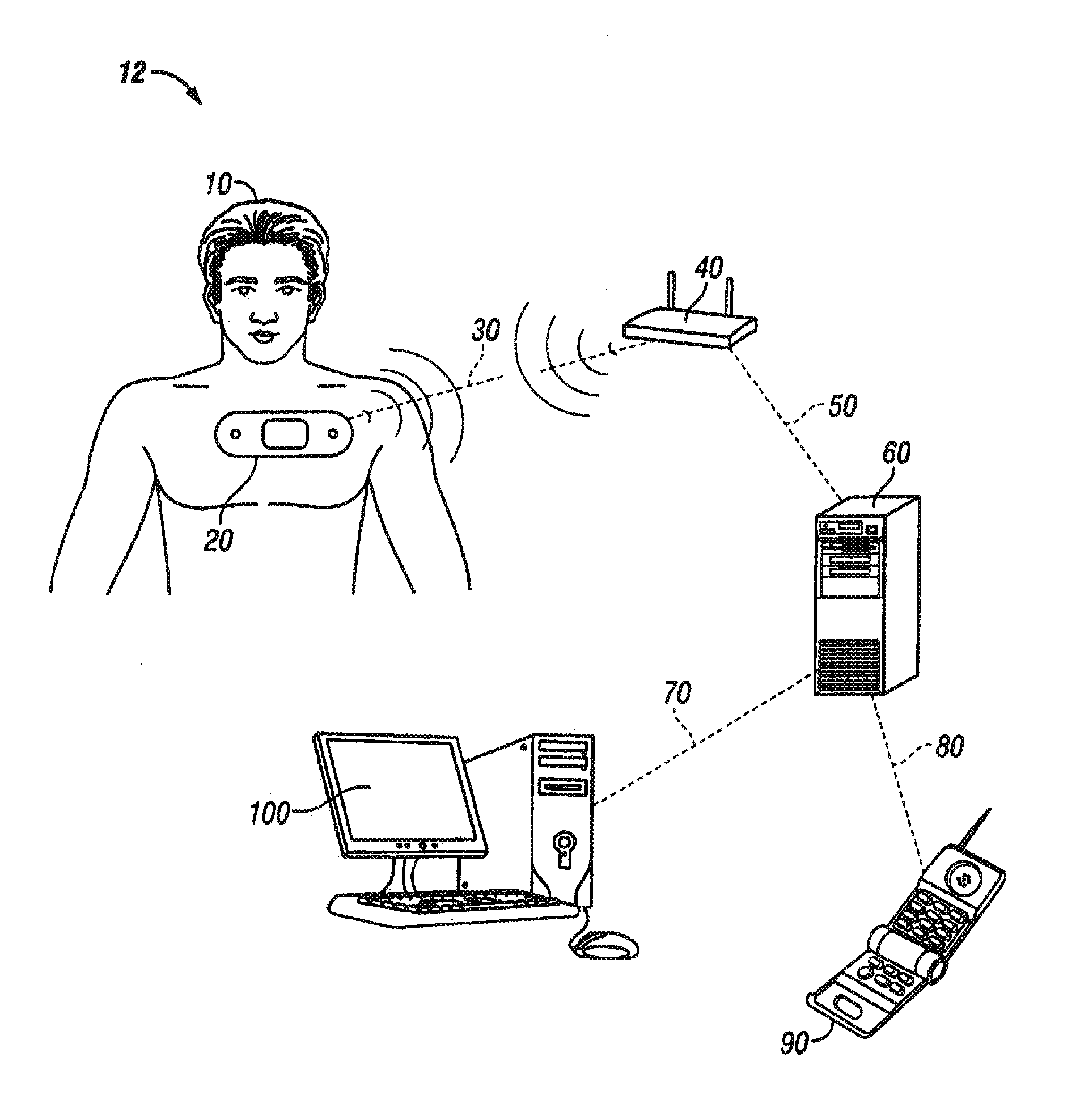
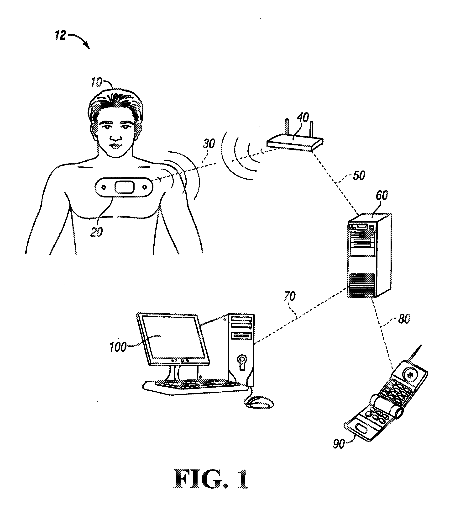
[0029]Continuous monitoring of patients in a hospital is desirable at least to ensure that patients do not suffer an un-noticed sudden deterioration in their condition or a secondary injury during their stay in the hospital. It is impractical to provide continuous monitoring by a clinician and cumbersome to connect sensors to a patient, which are then connected to a fixed monitoring instrument by wires. Furthermore, systems that sound an alarm when the measured value exceeds a threshold value may sound alarms so often and in situations that are not truly serious that such alarms are ignored by clinicians.

[0030]Measuring vital signs is difficult to do on a continuous basis. Accurate measurement of cardiac pulse, for example, can be done using an electrocardiograph (ECG or EKG) to detect the electrical activity of the heart. An EKG machine may use up to 10 electrodes placed at various points on the body to detect various signals associated with the heart function. Another common piece...


PUM


Abstract

Systems and methods of reducing false alarms associated with a vital-sign monitor are disclosed. One or more data samples of a vital sign of a patient are generated at a first sampling rate in a normal mode of operation. Whether the one or more data samples satisfy an alert condition is determined. An alert mode of operation is entered into if the alert condition is satisfied. One or more additional data samples of the vital sign are generated at a second sampling rate higher than the first sampling rate in the alert mode.

Description

CROSS-REFERENCES TO RELATED APPLICATIONS[0001]The following applications disclose certain common subject matter with the present application: A Vital-Signs Monitor with Encapsulation Arrangement, docket number 080624-0612; A Vital-Signs Monitor with Spaced Electrodes, docket number 080624-0623; A Vital-Signs Patch Having a Strain Relief, docket number 080624-0624; A Temperature Probe Suitable for Axillary Reading, docket number 080624-0625; System and Method for Monitoring Body Temperature of a Person, docket number 080624-0626; A System and Method for Storing and Forwarding Data from a Vital-Signs Monitor, docket number 080624-0627; A System and Method for Conserving Battery Power in a Patient Monitoring System, docket number 080624-0629; A System and Method for Saving Battery Power in a Patient Monitoring System, docket number 080624-0630; A System And Method for Tracking Vital-Signs Monitor Patches, Docket Number 080624-0631; A System And Method for Location Tracking of Patients ...

Claims


Application Information

Patent Timeline
Patent Type & Authority Applications(United States)
IPC IPC(8): A61B5/00G16H40/67
CPCA61B5/0008A61B5/6833G06F19/3418A61B5/72G08B21/0211G08B25/006A61B2560/0412A61B5/746A61B5/002G16H40/67A61B5/0002A61B5/01A61B5/02055A61B5/021A61B5/024A61B5/0816A61B5/7278A61B5/7282A61B2560/0475
Inventor PAQUET, PIERRELEWIS, STEPHEN
Owner CAREFUSION 303 INC
Why Eureka
Try Eureka