Supercharge Your Innovation With Domain-Expert AI Agents!

Low pressure control for signaling a time delay for ice making cycle start up

a low pressure control and time delay technology, applied in the field of automatic ice making machines, can solve the problems of compressor noise and bulk, large amount of heat and noise generated by compressors and condensers, and poor use of bulk space by normal ice machines, so as to reduce the excessive starting cycle

Inactive Publication Date: 2012-02-09
PENTAIR FLOW SERVICES
View PDF14 Cites 5 Cited by
  • Summary
  • Abstract
  • Description
  • Claims
  • Application Information

AI Technical Summary

Benefits of technology

[0024]Another feature is to monitor the high pressure control (HPC) on the condensing unit. When the high pressure control opens the control board will delay the condensing unit from restarting for a time limit of around 60 minutes. This allows the compressor to cool down and reduce excessive starting cycles also. The control will indicate on the display of the ice machine that it is in a time delay mode for the servicer to check out any problems on the condensing up on the roof.

Problems solved by technology

In a typical automatic ice making machine, the compressor and condenser unit generates a large amount of heat and noise.
Another problem with having the ice machine out where the ice is needed is that in many food establishments, space out by the food service area is at a premium, and the bulk size of a normal ice machine is poor use of this space.
While a typical remote ice making machine solves the problem of removing heat dissipated by the condenser, it does not solve the problem of the noise and bulk created by the compressor.
One of the main drawbacks of these prior systems is that the long length of the refrigerant lines needed for remote operation causes inefficiency during the harvest mode.
As it travels, the hot gas loses much of its heat to the lines' surrounding environment.
This results in a longer and more inefficient harvest cycle.
In addition, at long distances and low ambient temperatures, the loss may become so great that the hot gas defrost fails to function properly at all.
However, these systems are designed for use with multiple evaporators in parallel, and would not function properly if only a single evaporator, or if multiple evaporators in series, were used.
These refrigeration systems would not be cost effective, and perhaps not even practicable, if they were applied to ice making machines.
Such a system would not be economical if applied to ice machines where different sets of refrigerant lines had to be installed between each of the locations of the various parts.
Moreover, if the compressor and its associated components were moved outdoors to be in close proximity to a remote condenser, the system would not be able to harvest ice at low ambient temperature because the receiver would be too cold to flash off refrigerant when desired to defrost the evaporators.
While electrical heating elements have proved satisfactory for harvesting ice from the evaporator, they add to the expense of the product.
The disadvantage of this system is that over time this creates excessive cycling of wear on the start and / or run capacitor(s), relays and contactors, due to short cycling which, in turn, causes heating up of the electrical components.
The present inventors have discovered that such component failures result from a lack of cool down time.

Method used


Image

  • Low pressure control for signaling a time delay for ice making cycle start up
  • Low pressure control for signaling a time delay for ice making cycle start up
  • Low pressure control for signaling a time delay for ice making cycle start up

Examples


Embodiment Construction

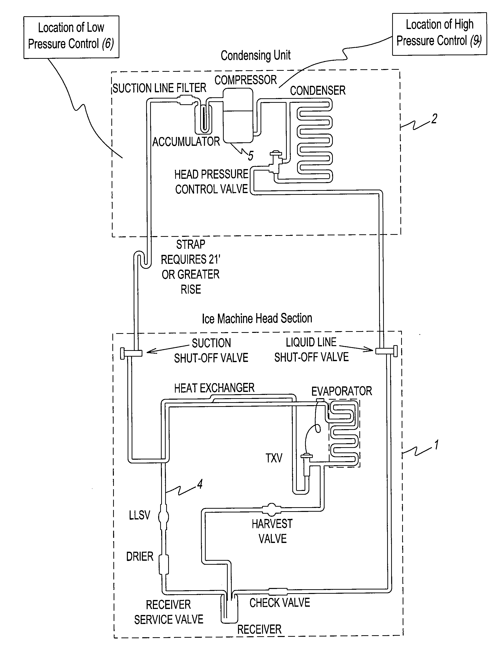
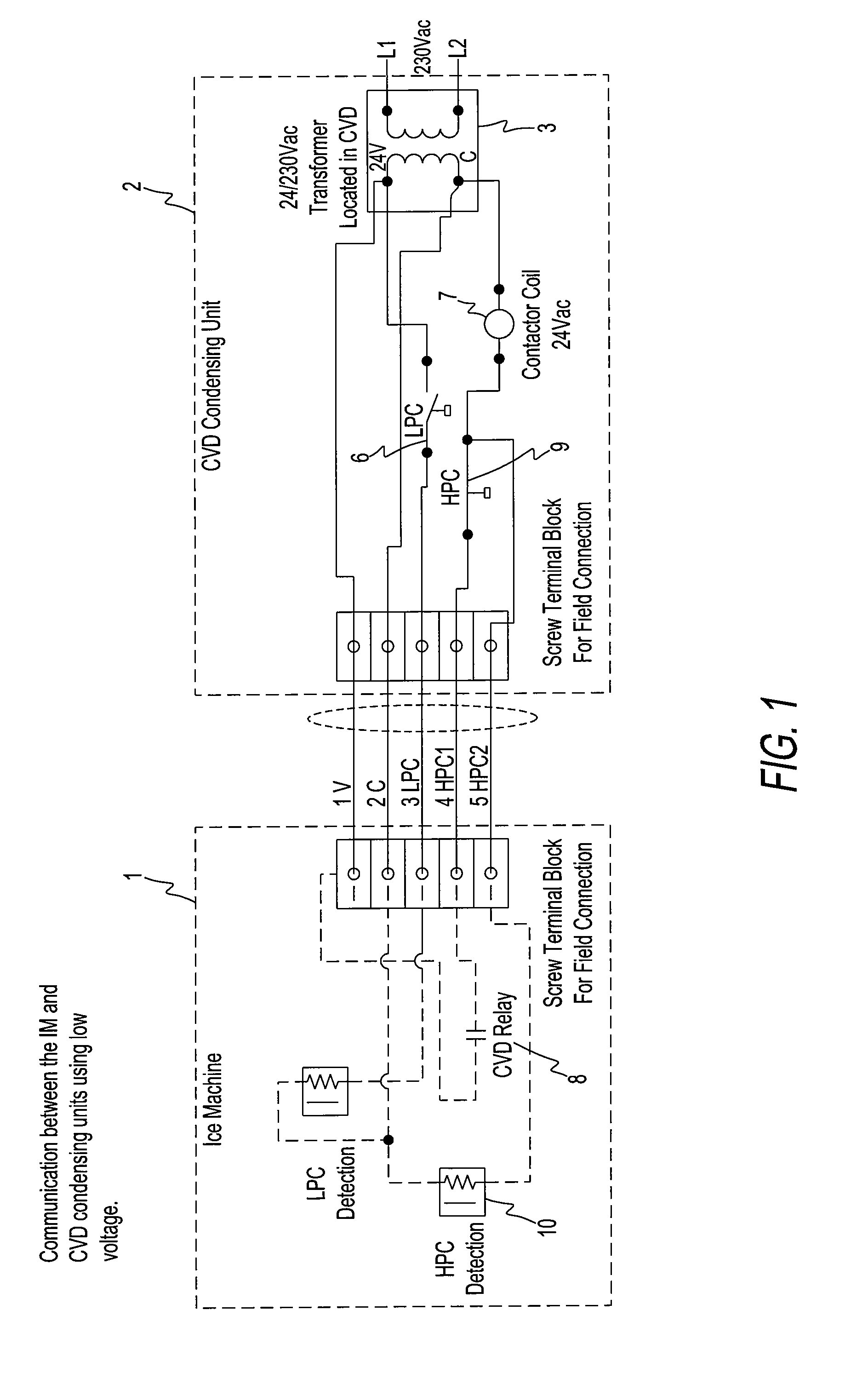
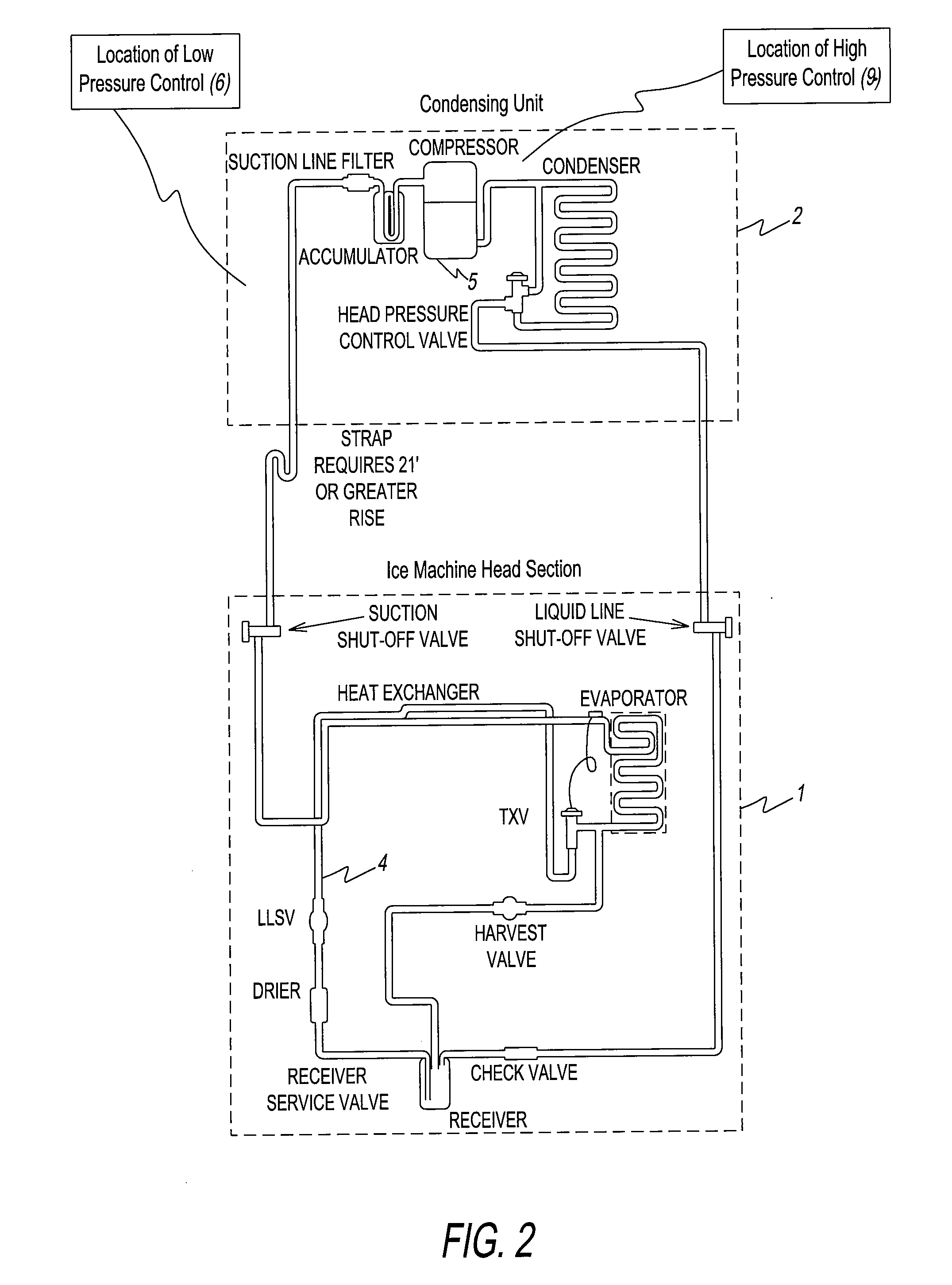
[0029]The system and method according to present disclosure is best described by reference to the attached figures, wherein FIGS. 1 and 2 depict the communication between an ice machine 1 and a CVD condensing unit 2. In particular, a low voltage transformer supplies 24 VAC 3 is disposed between ice machine 1 and CVD condensing unit 2 for the control circuit. When ice machine 1 is turned off, or in a full bin condition the liquid line solenoid valve 4 will close in ice machine 1. Compressor 5 will continue to “pump down” or pull the pressure down until the LPC (Low Pressure Control) switch 6 opens in condensing unit 2. This will indicate to the control board in ice machine 1 to open the contactor for compressor 5. Ice machine 1 will then open up CVD relay circuit 8 on the control board, which then opens up the 24 volt contactor coil 7 on condensing unit 2. HPC (High Pressure Control) 9 is in series between contactor coil 7 and CVD relay circuit 8 for protection against high refrigera...


PUM


Abstract

A method of making ice in an ice making machine comprising: (a) compressing vaporized refrigerant, cooling the compressed refrigerant to condense it into a liquid, feeding the condensed refrigerant through an expansion device and vaporizing the refrigerant in an evaporator to create freezing temperatures in an ice-forming mold to freeze water into ice in the shape of mold cavities during an ice making mode; (b) heating the ice making mold to release the ice therefrom in a harvest mode by separating vaporous and liquid refrigerant within a receiver interconnected between the condenser and the expansion device and feeding vapor from the receiver to the evaporator, wherein the ice-forming mold, evaporator and receiver are disposed in an ice machine unit, and the compressor and condenser are disposed in a condensing unit; (c) determining if the ice making machine is on and if an ice bin switch is closed: if the ice machine is on and the bin switch is closed, then check a low pressure switch: if the low pressure switch is not closed, then return to step (i) above; or if the low pressure switch is closed, then set a time delay for a predetermined time delay; and (d) determining if the predetermined time delay has elapsed: if the predetermined time delay has elapsed, then return to step (d); or if the predetermined time delay has elapsed, then initiate another the ice making mode.

Description

CROSS-REFERENCED APPLICATIONS[0001]This application claims priority to U.S. Provisional Application Ser. No. 61 / 370,420, filed on Aug. 3, 2010, which is incorporated herein by reference in its entirety.BACKGROUND[0002]1. Field[0003]The present disclosure relates to automatic ice making machines, and more particularly to an automatic ice making machine where the ice making evaporator is defrosted in a harvest mode by cool refrigerant vapor and where a low pressure control is used to signal a time delay before the ice machine starts up a new ice production mode or freeze cycle.[0004]2. Discussion of the Background Art[0005]Automatic ice making machines rely on refrigeration principles well-known in the art. During an ice making mode, the machines transfer refrigerant from the condensing unit to the evaporator to chill the evaporator and an ice-forming evaporator plate below freezing. Water is then run over or sprayed onto the ice-forming evaporator plate to form ice. Once the ice has ...

Claims


Application Information

Patent Timeline
Patent Type & Authority Applications(United States)
IPC IPC(8): F25C5/08
CPCF25C1/04F25C5/10F25C2700/02F25C2600/04F25C2600/02
Inventor MUELLER, LEE GERARDERBS, DARYL G.
Owner PENTAIR FLOW SERVICES
Features
  • R&D
  • Intellectual Property
  • Life Sciences
  • Materials
  • Tech Scout
  • Unparalleled Data Quality
  • Higher Quality Content
  • 60% Fewer Hallucinations
Learn More