Paperboard sheet slitter-scorer apparatus and control method for correcting the positions of slitter knives and scorers thereof

a technology of slitter-scorer and paperboard, which is applied in the direction of metal working apparatus, mechanical working/deformation, etc., can solve the problems of significant time and labor, reducing the width-direction dimension of sheets, etc., and achieves the effect of effective positioning the scorer in the desired scoring position, reducing time and labor, and uniform width dimensions

Inactive Publication Date: 2012-02-09
ISOWA IND CO LTD
View PDF4 Cites 11 Cited by
  • Summary
  • Abstract
  • Description
  • Claims
  • Application Information

AI Technical Summary

Benefits of technology

[0011]According to the present invention thus constituted, for the slitter knives in the utilized slitter, the amount of positional correction in the width direction is calculated according to the amount of shearing by the slitter knives relative to an initial position, together with the desired width dimension of the paperboard sheet; the slitter knives are positioned at positions based on this calculated correction amount, thereby enabling effective positioning of the slitter knives in the width direction so that a desired sheet width can be obtained. As a result, a major reduction of time and labor can be achieved for initial adjustments during machine installation.
[0013]According to the present invention thus constituted, positioning of scorers in the width dimension can be effectively performed. As a result, a major reduction of time and sheet loss can be achieved for initial adjustments at the time of machine installation.
[0015]According to the present invention thus constituted, positional control of slitter knives and scorers can be achieved by a simple control. Also, because the first and second correction amounts are corrected so as to place the utilized scorers and slitter knives based on the mechanical center, it becomes possible to position a slitter knife positioned at the furthest edge on one side of the width direction and a slitter knife positioned at the furthest edge on the other side of the width direction symmetrically about the mechanical center, thereby achieving a uniform width dimension for the trim cut off by the respective slitter knives. The paperboard sheets cut at the outermost side can therefore be prevented from becoming rejected sheets due to loss of trim on one side in the narrow width when a difference occurs between the width dimensions of the trim on the two sides during manufacturing.
[0018]According to the present invention thus constituted, paperboard sheet of a desired sheet width can be obtained with higher accuracy.
[0020]According to the present invention thus constituted, a slitter knife and scorer correction amounts are calculated relative to an initial position based on the desired paperboard sheet dimension in the width direction for the slitter knife of the utilized slitter; since the slitter and scorer are positioned at a position based on this calculated correction amount, it is possible to position the slitter knife effectively in the width direction so as to obtain a desired sheet width; it is also possible to effectively position the scorer in a desired scoring position. As a result, a major reduction in time and labor can be achieved when making initial adjustments at the time of machine installation. Also, because the first and second correction amounts are corrected so as to place the utilized scorers and slitter knives based on the mechanical center, it becomes possible to position a slitter knife positioned at the furthest edge on one side of the width direction and a slitter knife positioned at the furthest edge on the other side of the width direction symmetrically about the mechanical center, thereby achieving a uniform width dimension for the trim cut off by the respective slitter knives. Therefore the width dimension of trims cut by the respective slitter knives are respectively uniform, such that serpentine motion by the paperboard sheet in the supply direction during manufacturing can be prevented.
[0021]The present invention enables effective positioning of slitter knives in the width direction so that paperboard sheets of a desired sheet width can be obtained. Positioning of scorers can also be effectively performed in the width direction to perform scoring work at desired positions on the paperboard sheet.

Problems solved by technology

However, it normally occurs that sheets are sheared due to factors such as slitter knife thickness, reducing the width-direction dimension of sheets after paperboard sheet splitting (after slitting) to smaller than the desired sheet dimension.
This presented the problem that significant time and labor are required for such adjustment and operations by operators.

Method used


Image

  • Paperboard sheet slitter-scorer apparatus and control method for correcting the positions of slitter knives and scorers thereof
  • Paperboard sheet slitter-scorer apparatus and control method for correcting the positions of slitter knives and scorers thereof
  • Paperboard sheet slitter-scorer apparatus and control method for correcting the positions of slitter knives and scorers thereof

Examples


Embodiment Construction

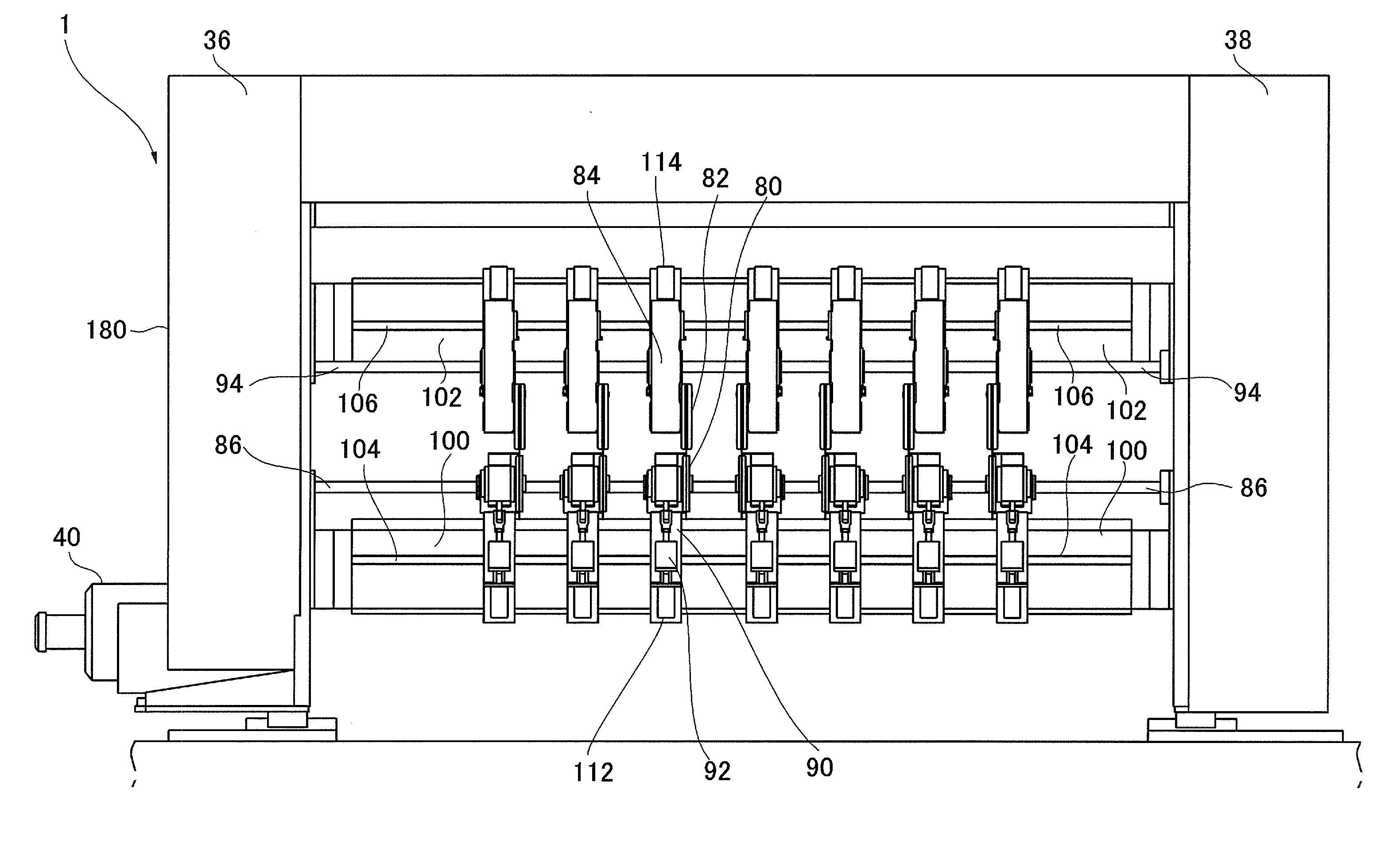
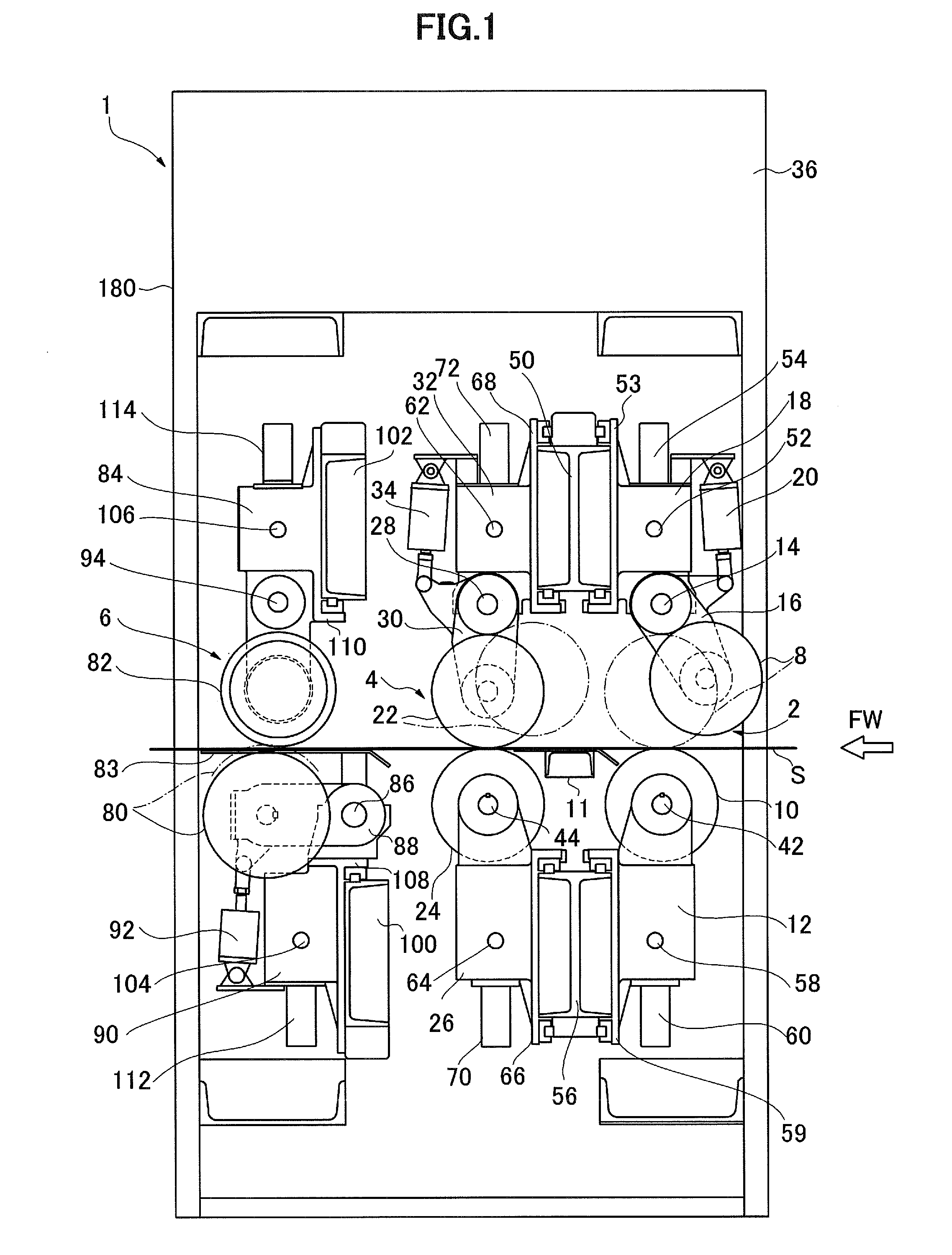
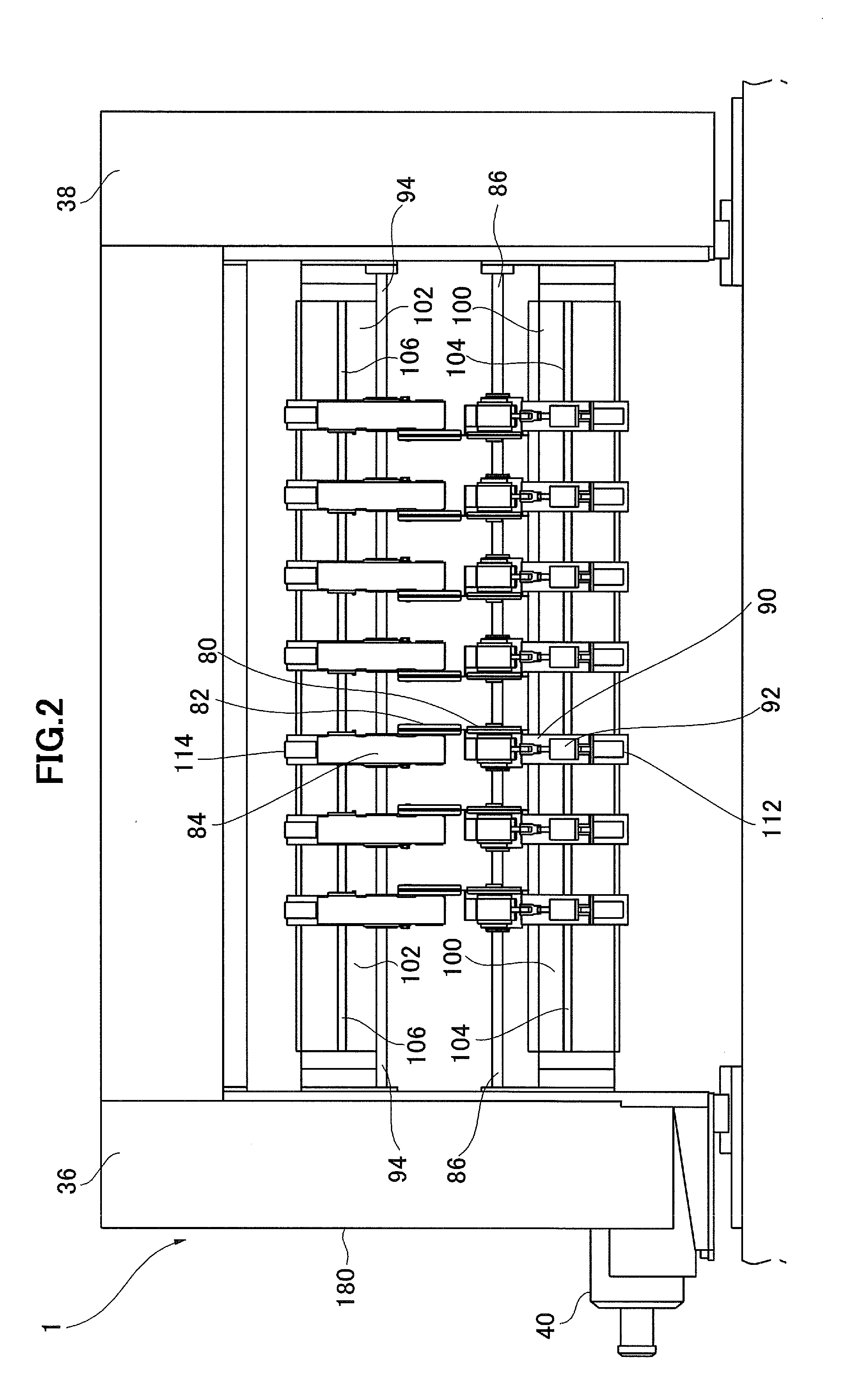
[0031]Next, referring to the attached drawings, a slitter-scorer apparatus according to an embodiment of the present invention will be described. First, referring to FIGS. 1 through 3, the basic structure of a slitter-scorer apparatus according to an embodiment of the present invention will be described. FIG. 1 is an overview side elevation showing a summary of a slitter-scorer apparatus according to an embodiment of the present invention; FIG. 2 is an overview front elevation showing a summary of a slitter-scorer apparatus according to an embodiment of the present invention; FIG. 3 is a front elevation showing an example of a slitter knife used in a slitter-scorer apparatus according to an embodiment of the present invention.

[0032]As shown in FIG. 1, Reference Numeral 1 indicates a slitter-scorer apparatus according to the present embodiment. This slitter-scorer apparatus 1 is provided on a paperboard sheet supply line at the dry end of a corrugator; a single facer, double facer, o...


PUM


Abstract

A slitter-scorer apparatus is provided, capable of effectively positioning slitter knives in the width direction so that a paperboard sheet of a desired sheet width can be obtained. The slitter scorer apparatus 1 of the present invention comprises a plurality of slitters 6 having slitter knives 80 and 82 paralelly disposed in the width direction relative to the supply direction of a paperboard sheet, for cutting the sheet; slitter width-direction moving means 90, 112, 104, 84, 114, and 16 for respectively independently moving the plurality of slitters in the width direction of the sheet; and a control means for selecting a utilized slitter from among the plurality of slitters based on a production order, calculating a width-direction correction amount relative to an initial position based on the desired paperboard sheet width-direction dimension according to the amount of shearing by the slitter knife, and controlling the slitter width-direction moving means so as to position the slitter knives at a position based on that calculated correction amount.

Description

BACKGROUND OF THE INVENTION[0001]1. Field of the Invention[0002]The present invention relates to a cardboard sheet slitter-scorer apparatus and control method for correcting the positions of slitter knives and scorers thereof, and more particularly to a paperboard sheet slitter-scorer apparatus in which a plurality of slitters are placed in the width direction.[0003]2. Description of the Related Art[0004]Known conventional slitter-scorer apparatuses include those in which a slitter knife is positioned in a predetermined position in the width direction, in accordance with the number of manufactured sheets, to perform cutting work (e. g., Japanese Patent Publication No. 3717167).[0005]Japanese Patent Examined Publication No. 1-014017 discloses a tool positioning method whereby multiple tools are transferred from a standby area to a setting area and positioned at a predetermined position on a sheet within the setting area using as a reference the position of an origin point between the...

Claims


Application Information

Patent Timeline
Patent Type & Authority Applications(United States)
IPC IPC(8): B26D11/00
CPCB26D1/245B26D3/085B31F1/10B26D7/2635B26D5/00Y10T83/0222
Inventor MOMONAKA, HIROKISUZUKI, MICHIOSAWAYAMA, KAZUYA
Owner ISOWA IND CO LTD
Why Eureka
Try Eureka