Intake manifold and seal

a technology of manifold and seal, which is applied in the direction of machines/engines, combustion air/fuel air treatment, and feed systems, etc., can solve the problems of increasing the complexity reducing the efficiency and complicating the coupling of the engine manifold to the cylinder head. , to achieve the effect of minimizing the required number of components and minimizing the assembly time of the manifold assembly

Inactive Publication Date: 2012-02-09
DANA AUTMOTIVE SYST GRP
View PDF11 Cites 2 Cited by
  • Summary
  • Abstract
  • Description
  • Claims
  • Application Information

AI Technical Summary

Benefits of technology

[0006]Presently provided by the invention, a manifold assembly for an engine that minimizes a required number of components, minimizes a time of assembly of the manifold assembly, and militates against a rotation of an engine manifold, has surprisingly been discovered.

Problems solved by technology

Such manifold assemblies require a plurality of components, undesirably increasing the complexity of the manifold assembly.
Coupling the manifold assembly including the plurality of components may become an arduous or a time consuming task.
The engine manifold having a plurality of manifold inlets or a plurality of manifold outlets further complicates coupling the engine manifold to the cylinder head, as simultaneous attention must be given to each of the manifold inlets or each of the manifold outlets.
The plurality of components of the manifold assembly undesirably increases an assembly time and an amount of required component manipulation during assembly of the manifold assembly.
During transportation of the partially assembled engines and non-operational assembled engines, engine components may move in an undesirable manner.
A rotation of the engine manifold during transportation may result in damage to the seal disposed between the cylinder head and the engine manifold.
Further, correction of a positioning of the engine manifold may result in an undesirable increase in a duration of the engine assembling process.

Method used


Image

  • Intake manifold and seal
  • Intake manifold and seal
  • Intake manifold and seal

Examples


Embodiment Construction

[0016]It is to be understood that the invention may assume various alternative orientations and step sequences, except where expressly specified to the contrary. It is also to be understood that the specific devices and processes illustrated in the attached drawings, and described in the following specification are simply exemplary embodiments of the inventive concepts defined in the appended claims. Hence, specific dimensions, directions or other physical characteristics relating to the embodiments disclosed are not to be considered as limiting, unless the claims expressly state otherwise.

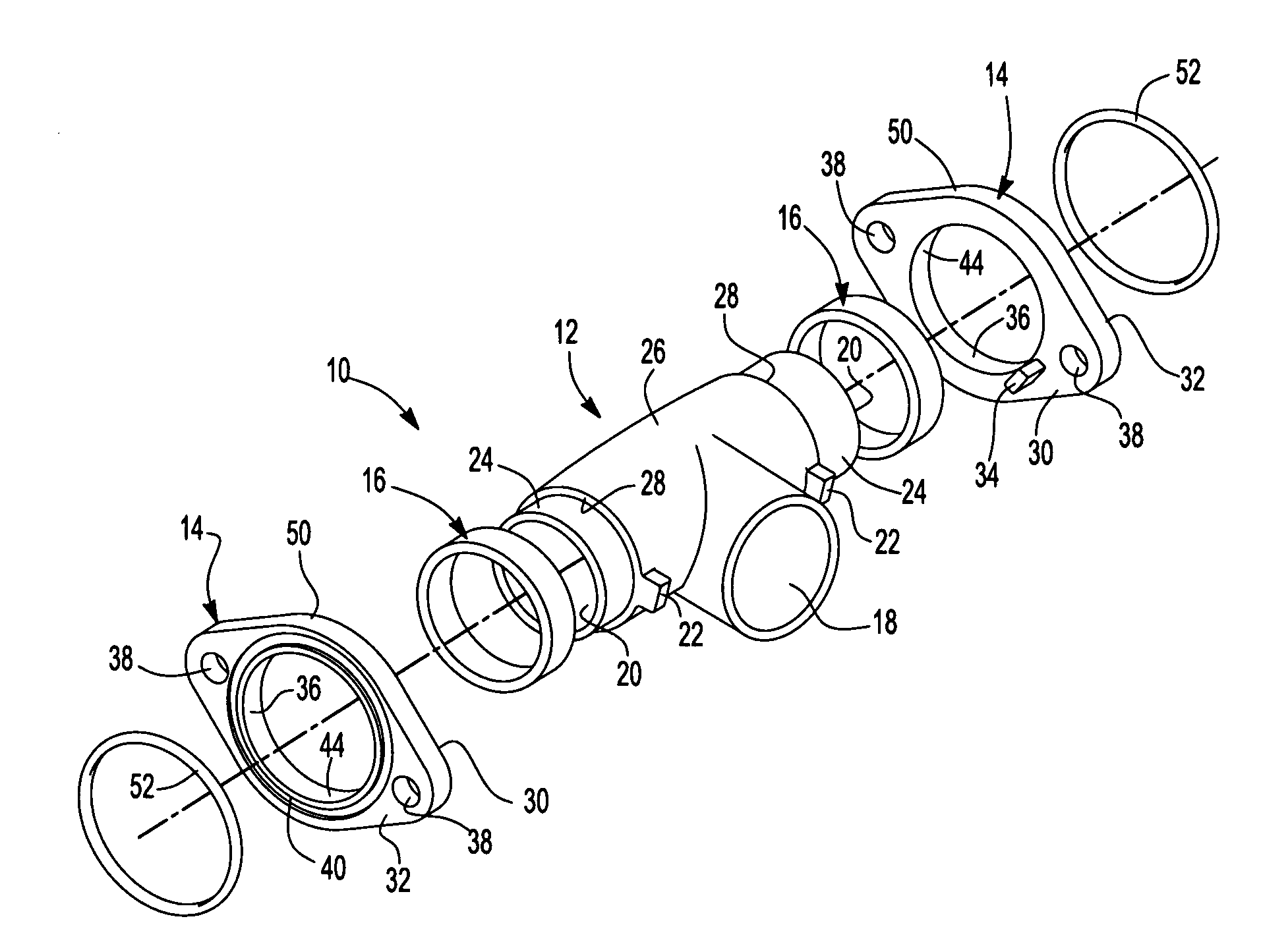
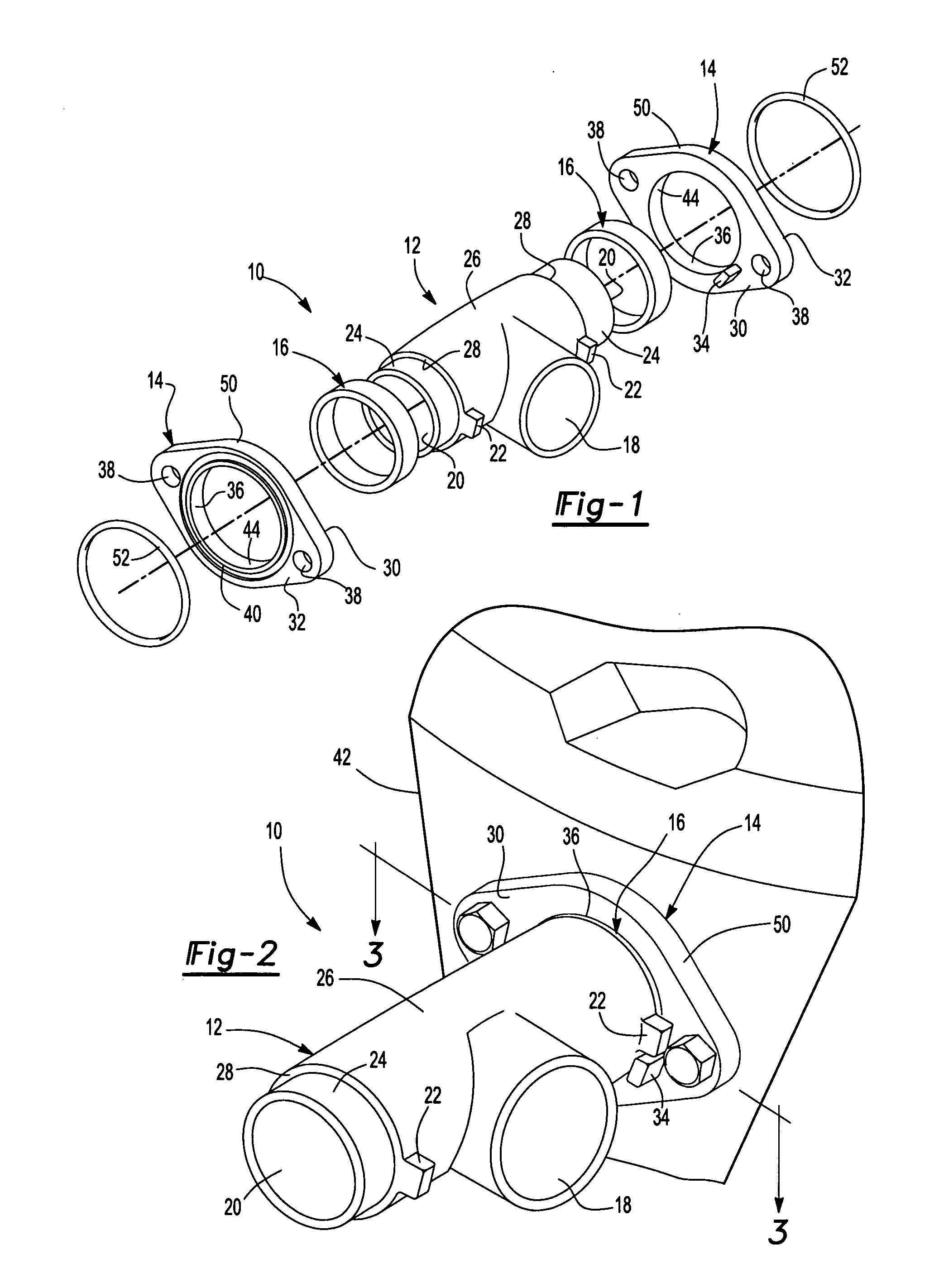
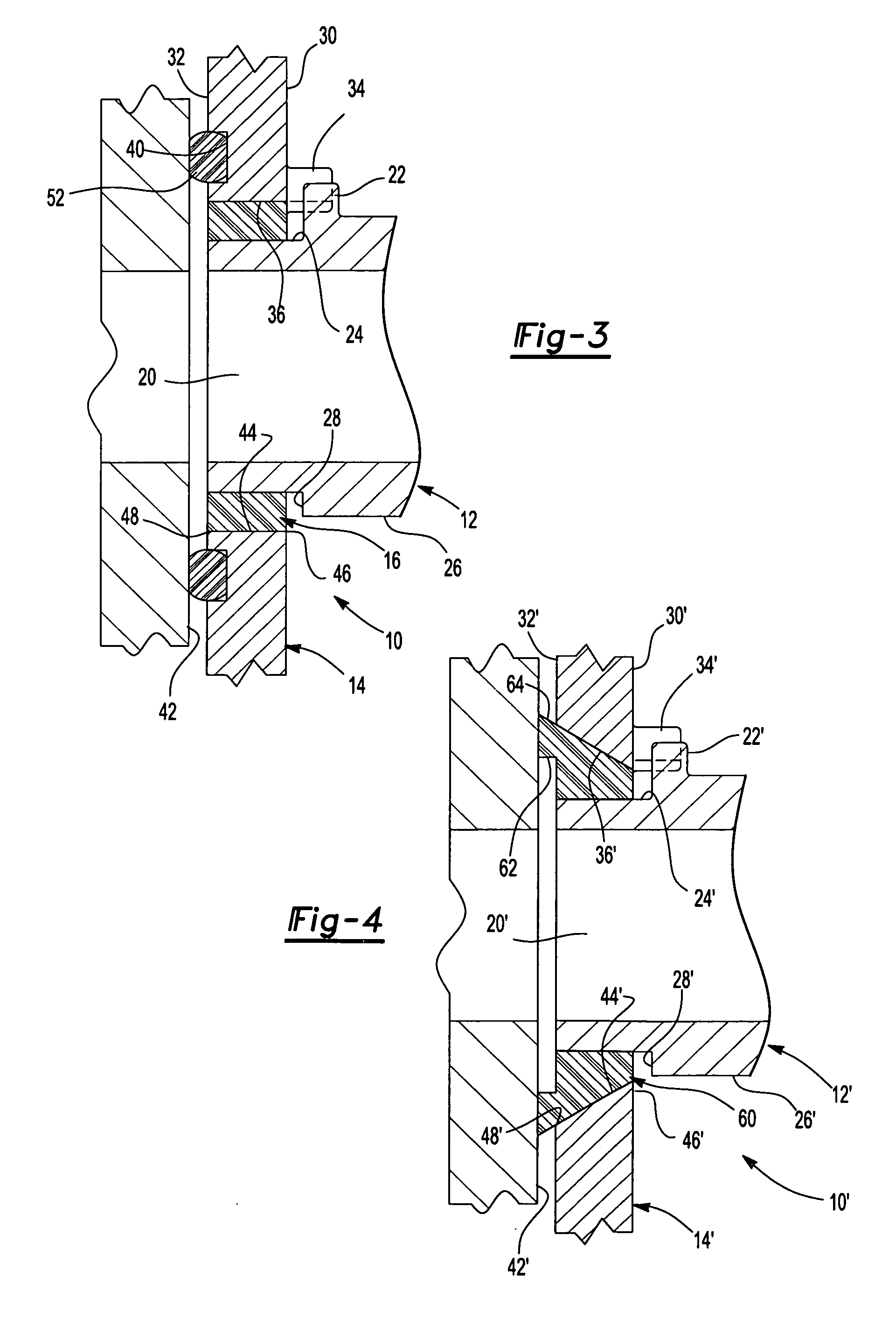
[0017]FIGS. 1-3 illustrate a manifold assembly 10 for an engine according to an embodiment of the present invention. The manifold assembly 10 includes an engine manifold 12, a mounting collar 14, and a resilient seal 16. As shown, the manifold assembly 10 is an intake manifold assembly, but the manifold assembly 10 may be an exhaust manifold assembly.

[0018]The engine manifold 12 has an inlet 18, a...


PUM


Abstract

A manifold assembly is provided having an engine manifold, a mounting collar, and a resilient seal. The mounting collar is disposed on the engine manifold and the resilient seal is disposed between the engine manifold and the mounting collar. The engine manifold has an inlet, an outlet, and a primary protuberance formed on an outer surface of the engine manifold. The mounting collar has a secondary protuberance and is disposed on the engine manifold. The resilient seal is disposed between the engine manifold and the mounting collar. The primary protuberance abuts the secondary protuberance. The manifold assembly for an engine minimizes a required number of components, minimizes a time of assembly of the manifold assembly, and militates against a rotation of the engine manifold.

Description

FIELD OF THE INVENTION[0001]The present invention relates to an engine manifold and a mounting collar for the engine manifold having a resilient seal disposed between the mounting collar and the engine manifold.BACKGROUND OF THE INVENTION[0002]Manifold assemblies typically include at least one seal to militate against an escape of intake gases and exhaust gases. An engine manifold typically compresses a seal disposed between the engine manifold and a cylinder head. The engine manifold is urged towards the cylinder head by a mounting collar disposed on the engine manifold. An adjustable fastener coupling the mounting collar to the cylinder head permits an urging force to be varied. Upon compression of the seal, the engine manifold is rigidly coupled to the cylinder head, and little relative movement between the engine manifold and the cylinder head is afforded. Such manifold assemblies require a plurality of components, undesirably increasing the complexity of the manifold assembly.[...

Claims


Application Information

Patent Timeline
Patent Type & Authority Applications(United States)
IPC IPC(8): F02M35/10
CPCF02M35/10078
Inventor SCHWEIGER, DAVID J.
Owner DANA AUTMOTIVE SYST GRP
Why Eureka
Try Eureka